The Fundamentals of Sizing a Low Loss Header
When approaching the task of sizing a low loss header, the primary objective is to create a zone of low pressure drop where the primary boiler circuit and the secondary distribution circuit can operate independently. This hydraulic decoupling is critical in modern commercial heating systems where variable speed pumps are standard. Without accurate sizing, you risk high-velocity turbulence or insufficient mixing, both of which can lead to ghost pumping or inefficient heat transfer. Engineers must calculate the total system flow rate, typically in cubic metres per hour, to determine the appropriate vessel diameter. The vessel must be large enough to ensure that the vertical velocity of the water within the header remains low, usually below 0.1 to 0.2 metres per second, to facilitate effective separation of air and dirt particles in accordance with BSRIA BG29 and BG50 guidelines.
Precision in sizing a low loss header prevents the common issue of 'temperature creep' where the return temperature to the boiler becomes too high, preventing condensing boilers from operating at their peak efficiency. UKGP Industrial specializes in providing flanged and threaded solutions that accommodate these specific hydraulic requirements. By selecting a header that matches the peak volumetric flow of the system, contractors can ensure that the neutral point remains stable regardless of how many secondary zones are calling for heat. A well-sized header acts as a buffer and a settling chamber, which is why UKGP units are frequently specified for plant rooms ranging from 40 kW to 2000 kW. Our technical team often assists M&E consultants in verifying these calculations to ensure the finished installation meets the rigorous standards expected in UK commercial building services and large-scale residential blocks.
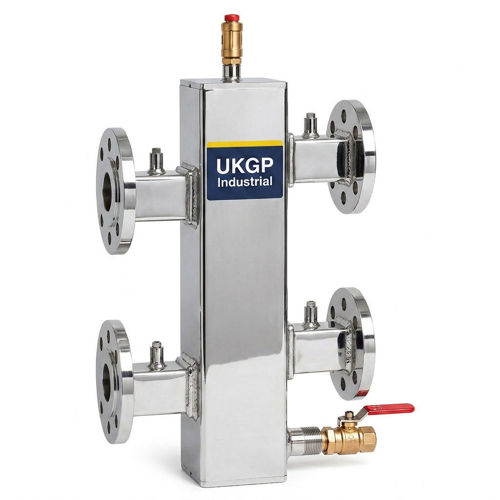
Furthermore, the physical dimensions of the header must account for more than just the pipe diameter. The height of the vessel and the spacing between the four main flow and return ports are crucial for maintaining the 'neutral' thermal zone. If the ports are too close, the kinetic energy of the incoming water can bridge the gap, effectively bypassing the low-loss benefit. This is why UKGP low loss headers are manufactured with internal baffle plates or specific volumetric ratios to ensure total hydraulic equilibrium. When you request a quote for a UKGP header, you are investing in a component designed to mitigate the risks of pump conflict and sensor errors. With a 2-year warranty and a standard 2-3 week lead time, our headers provide the reliability needed for fast-paced commercial projects where system longevity and energy efficiency are the top priorities for the client.
- Calculate total primary and secondary flow rates in m3/h.
- Maintain low internal vertical velocity (0.1m/s - 0.2m/s).
- Ensure port spacing matches manufacturer hydraulic charts.
- Consider future-proofing for potential system expansion.
Applying the 3:1 Pipe Rule for Hydraulic Stability
The 3:1 rule is a time-tested industry standard used when sizing a low loss header to ensure sufficient internal volume. Essentially, the rule dictates that the diameter of the header vessel should be three times the diameter of the largest connecting pipe. For example, if your primary flow and return pipes are 50mm (DN50), the low loss header body should ideally have a diameter of 150mm. This ratio is designed to significantly reduce the velocity of the water as it enters the vessel, allowing for the transition from dynamic pressure to static pressure. While modern CFD (Computational Fluid Dynamics) modelling allows for more nuanced designs, the 3:1 rule remains a reliable benchmark for HVAC engineers and plant-room designers working on commercial systems where simplicity and robustness are preferred over complex bespoke fabrications.
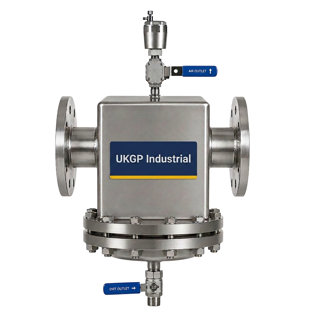
Adhering to this ratio assists in the de-aeration process, which is a key recommendation in CIBSE Guide AM14. By slowing the water down through the 3:1 cross-sectional area increase, micro-bubbles are given the opportunity to rise to the top of the header where they can be vented via an automatic air vent. Similarly, heavy magnetic and non-magnetic debris can settle at the base for removal via a drain valve. UKGP Industrial headers are built with these principles in mind, often incorporating features found in air and dirt separators to provide a multi-functional component. When contractors follow the 3:1 rule, they find that the system commissioning phase is much smoother, as the hydraulic circuits remain balanced and easier to regulate. Our PN16 flanged units or BSP threaded options are all sized to provide this essential slowing of flow for maximum system protection.
It is important to note that while the 3:1 rule is a fantastic rule of thumb, engineers must also consider the '4:2' spacing principle, which relates to the vertical distance between the flow and return entries. This height ensures that thermal stratification is maintained, preventing the cooler return water from immediately mixing with the hot flow water and degrading the system's thermal performance. UKGP Industrial's range of units, covering 40 kW through to 2000 kW, are engineered to balance these volumetric ratios perfectly. By ensuring your specification follows these traditional sizing metrics, you reduce the risk of cavitation in secondary pumps and ensure the boiler's heat exchanger is not subjected to improper flow conditions. For a rapid turnaround on a compliant vessel, UKGP offers high-quality insulated headers that meet all current UK building regulations and safety standards.
- Vessel diameter should be 3x the inlet pipe diameter.
- Reduces water velocity to facilitate pressure equalization.
- Improves the efficiency of internal air and dirt separation.
- Reduces the risk of turbulence-induced noise in the plant room.
Impact of Incorrect Sizing on System Longevity
Selecting an undersized header is a common error that can lead to significant operational headaches. When sizing a low loss header too small, the water maintains a high velocity as it passes through the vessel. This prevents the primary and secondary pumps from being truly decoupled, leading to a situation where the pumps effectively 'fight' each other. This results in premature wear on pump bearings and can cause sensitive control valves to oscillate as they attempt to compensate for the erratic pressure changes. In large commercial installations, this lack of hydraulic stability can lead to uneven heating across different zones of a building, resulting in complaints from facility managers and increased energy consumption as the system struggles to find a steady state of operation.
Conversely, an oversized header, while less problematic than an undersized one, can lead to excessive thermal lag and unnecessary heat loss if not properly insulated. At UKGP Industrial, all our low loss headers come with a high-quality insulation jacket to minimize standing heat losses, ensuring compliance with Part L of the Building Regulations. Moreover, an oversized unit may take up valuable plant room footprint, which is often at a premium in London and Surrey refurbishments. The key is to find the 'Goldilocks' zone—a header that handles the peak flow with enough volume to ensure separation without being excessively bulky. Our 40-2000 kW range is tiered to ensure that whether you are working on a small commercial unit or a massive district heating scheme, there is a UKGP header that fits the technical requirements perfectly.
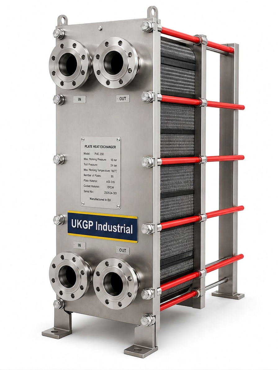
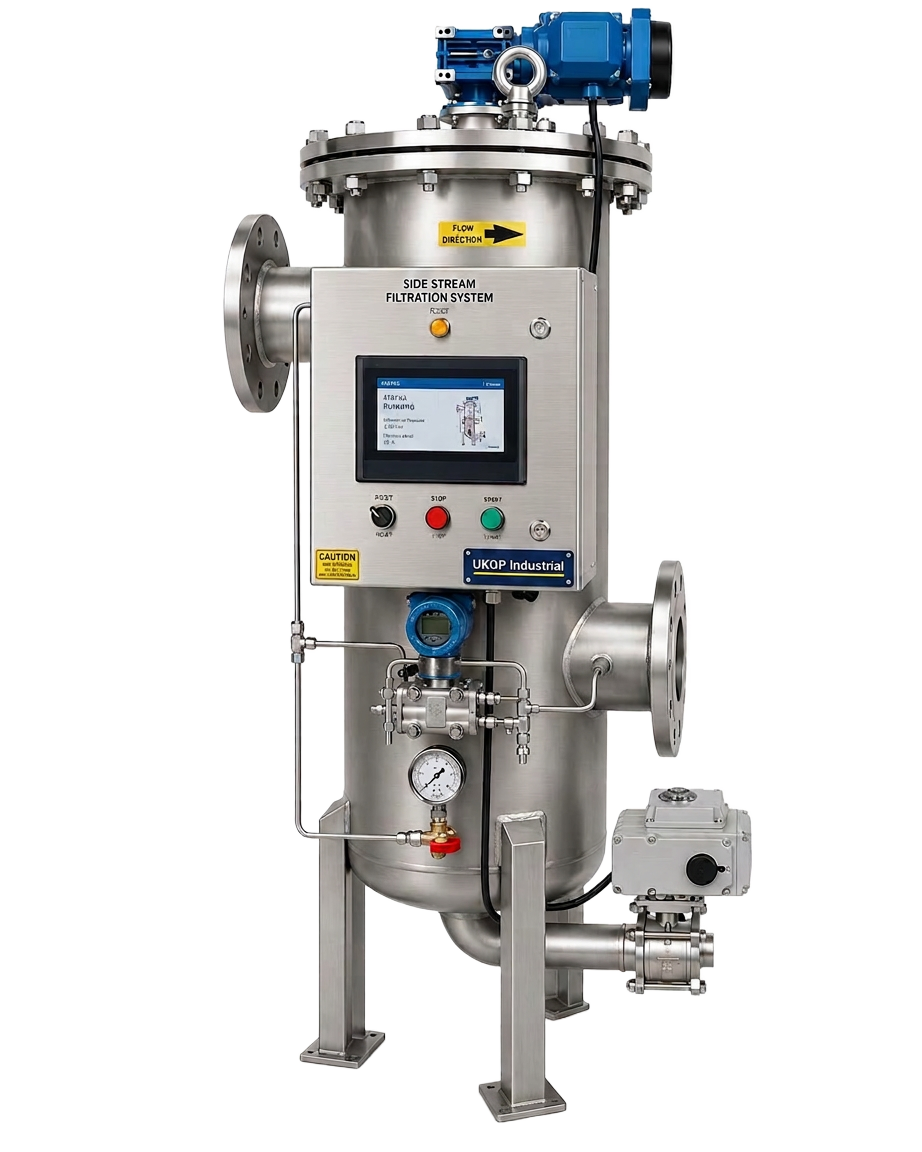
Effective water quality management also starts with the correct hydraulic conditions. If your low loss header is correctly sized, it facilitates the removal of magnetite, which is essential for protecting the plate heat exchanger and other sensitive components downstream. BSRIA BG50 highlights the importance of maintaining low-velocity zones to allow for effective solids precipitation. Using an undersized header will keep these particles in suspension, allowing them to circulate and cause erosive wear on pipework and components. By integrating a UKGP header alongside our chemical dosing pots and side stream filtration skids, you create a comprehensive protection strategy for the entire HVAC network. This holistic approach ensures that the project meets BS 8552 requirements for water sampling and system cleanliness, providing the client with a long-lasting and efficient heating or cooling solution.
- Undersizing causes pump conflict and hydraulic interference.
- High velocities prevent effective dirt and air separation.
- Oversizing adds unnecessary cost and plant-room footprint.
- Correct sizing protects downstream plate heat exchangers.
Technical Specifications and Material Selection
UKGP Industrial manufactures low loss headers from high-grade carbon steel, ensuring robust performance in demanding commercial environments. When sizing a low loss header for your project, material compatibility is paramount. Our headers are designed to withstand pressures associated with PN16 ratings, making them suitable for high-rise buildings and large-scale industrial complexes. The internal design of our headers often includes a per-forated baffle, which further aids in the calming of the water flow, enhancing the effects of the 3:1 pipe rule. This design ensures that the static pressure area is truly stagnant enough for bubbles to rise and grit to fall, regardless of whether the primary pump is operating at a different curve than the secondary distribution pumps.
The connection types available—BSP threaded for smaller systems and PN16 flanged for larger commercial outputs—allow for easy integration into existing or new pipework. Insulation is not an afterthought; each UKGP header is supplied with a tailored, removable insulation jacket. This is vital for maintaining the energy efficiency of the system and protecting plant room personnel from high-temperature surfaces. With a lead time of just 2-3 weeks, UKGP provides a competitive advantage for M&E contractors who need to maintain tight construction schedules without compromising on the quality or the engineering integrity of the hydraulic separation components. Our units are fully pressure tested before leaving our Surrey facility, ensuring they arrive on-site ready for immediate installation and commissioning.
In addition to the physical build, we provide comprehensive documentation to support the sizing a low loss header process. This includes flow rate charts, pressure drop curves, and dimensional drawings that can be easily dropped into CAD or BIM models. For engineers following BS EN 14917 or other relevant European standards, our headers offer the peace of mind that comes from a product engineered for the UK market. The 2-year warranty we offer is a testament to our confidence in the durability of our welding and material selection. When you choose a UKGP low loss header, you are choosing a product that has been refined through years of feedback from the UK's leading building services consultants and facility management professionals who demand the best in plant room performance.
- Carbon steel construction with PN16 or BSP connections.
- Integrated insulation jackets included as standard.
- Suitable for commercial loads from 40 kW to 2000 kW.
- 2-3 week lead time for standard and custom requirements.
Integrating Sensors and Transmitters in Header Design
A modern plant room relies on accurate data to maintain efficiency, and the low loss header is often the ideal location for system sensors. Because the water in the header is at a relatively low velocity and represents a mixed temperature of the system, it provides a stable environment for temperature sensors and pH probes. When sizing a low loss header, it is wise to specify additional tappings for these instruments. Monitoring the pH of the system water is a core component of BSRIA BG50 compliance, as localized corrosion can occur if the water chemistry drifts outside of the recommended parameters. Integrating pH sensors directly into the bypass or the header itself allows for real-time monitoring of the system health, preventing costly downtime.
UKGP Industrial can provide a range of pH sensor and transmitters that complement our low loss headers. By having these tappings pre-installed at the factory, installers save significant time and reduce the number of potential leak points in the system. The data captured from these sensors allows the building management system (BMS) to adjust chemical dosing precisely, rather than relying on manual, periodic testing. This proactive approach to maintenance is increasingly demanded by FM providers who are responsible for the long-term lifecycle costs of the boiler plant. A correctly sized header ensures that the sensors are reading a representative sample of the fluid, free from the interference of high-velocity bubbles or fast-moving debris that could damage sensitive probe glass.
In addition to pH monitoring, the low loss header is the critical point for placing the system's common flow temperature sensor. This sensor tells the boiler plant whether the secondary demand is being met. If the header is sized incorrectly, the sensor may provide a 'false' reading due to short-circuiting of the flow, leading to the boilers cycling frequently or failing to reach setpoint. By following the 3:1 sizing rule and choosing a UKGP vessel, you ensure the hydraulic conditions are perfect for both control and monitoring. Our commitment to supporting M&E contractors extends beyond just hardware; we provide the technical context needed to ensure that every sensor and valve works in harmony with the hydraulic separator for a truly intelligent plant room solution.
- Tappings available for pH sensors and temperature probes.
- Facilitates real-time water quality monitoring via BMS.
- Stable flow conditions ensure accurate sensor readings.
- Complies with BSRIA guidelines for water chemistry control.
Best Practices for Installation and Commissioning
Once you have finished sizing a low loss header and the unit has arrived on site, the installation phase must be handled with precision. UKGP headers should be installed vertically to take full advantage of the internal air and dirt separation capabilities. There must be sufficient clearance at the top for the automatic air vent and at the bottom for the flush-out drain valve. Our headers are designed for ease of mounting, but contractors must ensure that the supporting structure or floor can handle the weight of the vessel when full of water. Because our lead times are a short 2-3 weeks, contractors can often time the arrival of the header to coincide with the main plant installation, reducing the need for on-site storage and the risk of damage.
During the commissioning phase, it is vital to verify that the flow rates on both the primary and secondary sides are within the design parameters calculated during the sizing a low loss header stage. Using ultrasonic flow meters or fixed balancing valves, the engineer should confirm that the header is operating in the intended mode—whether that be a balanced flow, a primary surplus, or a secondary surplus. This verification is essential for satisfying the requirements of BSRIA BG29 pre-commission cleaning protocols. A correctly sized and installed UKGP header will exhibit a very low pressure drop across the body, which can be confirmed using the pressure gauge tappings typically provided on our commercial units. This data provides the final proof of a well-engineered hydraulic design.
Finally, ensure that the insulation jacket is fitted correctly after all connections have been leak-tested. An uninsulated header is a significant source of energy waste, and in a commercial plant room, it can affect the ambient temperature sensors and the efficiency of other equipment. UKGP Industrial headers are more than just steel vessels; they are a critical junction that determines the success of the entire HVAC strategy. By requesting a quote for a UKGP low loss header, you are partnering with a Surrey-based manufacturer that understands the pressures of UK construction. Our 2-year warranty and expert technical support ensure that from sizing to long-term operation, your system remains balanced, efficient, and compliant with all relevant CIBSE and BSRIA standards.
- Install vertically to enable air venting and dirt drainage.
- Verify primary and secondary flow rates during commissioning.
- Ensure the insulation jacket is snug to prevent heat loss.
- Utilize UKGP technical support for custom port orientations.
Frequently asked questions
What is the 3:1 pipe rule in header sizing?
- The 3:1 rule suggests that the diameter of the low loss header body should be three times the diameter of the largest connecting pipe to ensure water velocity is reduced sufficiently for hydraulic decoupling.
What range of outputs do UKGP low loss headers cover?
- We manufacture and supply headers for commercial systems ranging from 40 kW to 2000 kW, available in both flanged PN16 and threaded BSP connections.
Do your low loss headers come with insulation?
- Yes, all UKGP low loss headers are supplied with a tailored insulation jacket as standard to prevent heat loss and ensure compliance with energy efficiency regulations.
How long is the lead time for a UKGP header?
- Our standard lead time for low loss headers is 2-3 weeks, making us one of the fastest suppliers in the UK for high-quality plant room equipment.
Is a low loss header necessary for heat pump systems?
- Yes, they are highly recommended as they ensure the heat pump maintains its required minimum flow rate regardless of what is happening on the heating circuit side, protecting the compressor.