Low Loss Headers — Hydraulic Separators for Multi-Boiler Systems
What is a low loss header? It provides hydraulic separation between primary and secondary heating circuits, eliminating pump interference.
Description
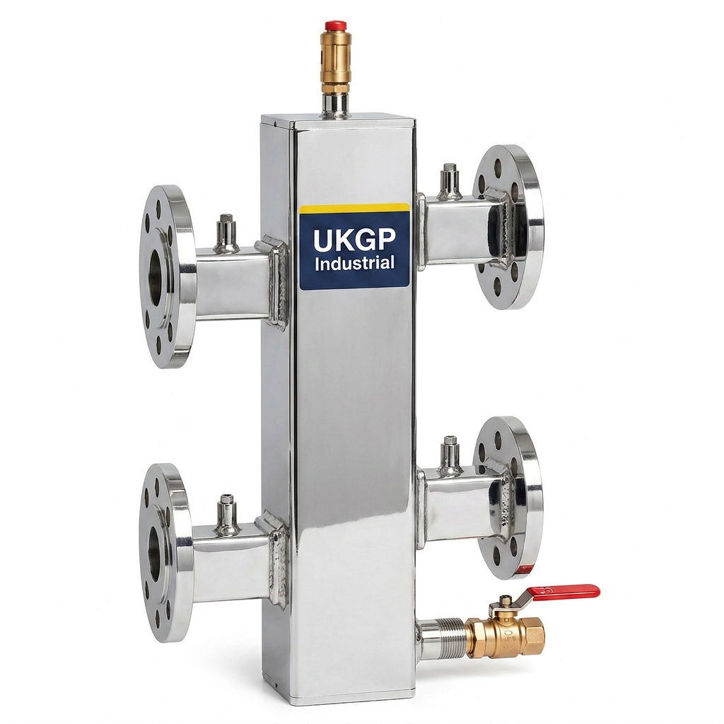
Low loss headers provide hydraulic separation between primary and secondary heating circuits, eliminating pump interference and ensuring balanced flow across multi-boiler installations.
UK stock · Same-day dispatch before 3pm · Trade accounts welcome
 UKGP · Industrial
UKGP-LLH · Bespoke specification
Sizes, performance & buy options
Decouple boiler and system flows so primary and secondary circuits optimise at best efficiency. Carbon steel body with Flamco Flexvent AAV and DN25 drain valve (high-power range). Not suitable for drinking water.
- Body
- Carbon steel
- HP rating
- 10 barg @ 110°C
- LP rating
- 6 barg @ 110°C
- Drain
- DN25 valve (HP)
Low Power · DN20 – DN25 (BSPP)
6 barg @ 110°C · BSPP female threaded
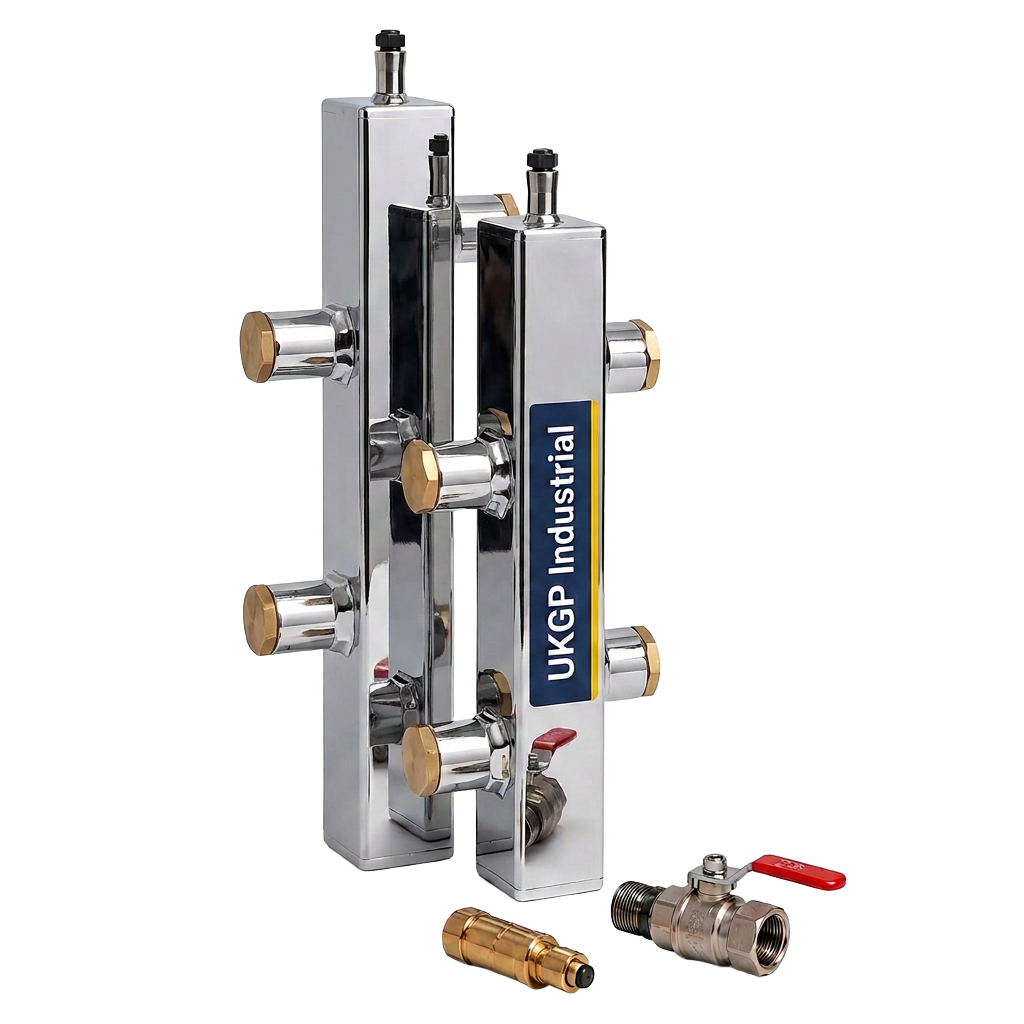
Carbon steel body, BSPP female threaded system connections with plugged air vent and drain.
| Size | Length | Body | Height | Flow | Power | Part code | Price | Buy |
|---|---|---|---|---|---|---|---|---|
| 200 mm | DN40 | 420 mm | 1.3 m³/h | 30 kW | UKGP-LLH-01 | £245 | ||
| 220 mm | DN50 | 460 mm | 2.0 m³/h | 50 kW | UKGP-LLH-02 | £275 |
UKGP-LLH-01
£245
- Length
- 200 mm
- Body
- DN40
- Height
- 420 mm
- Flow
- 1.3 m³/h
- Power
- 30 kW
UKGP-LLH-02
£275
- Length
- 220 mm
- Body
- DN50
- Height
- 460 mm
- Flow
- 2.0 m³/h
- Power
- 50 kW
Low Power · DN32 – DN50 (BSPT)
6 barg @ 110°C · BSPT male threaded
Carbon steel body, BSPT male threaded connections. Brass thermocouple pocket fitted in ½" socket.
| Size | Length | Body | Height | Flow | Power | Part code | Price | Buy |
|---|---|---|---|---|---|---|---|---|
| 260 mm | DN65 | 520 mm | 3.0 m³/h | 70 kW | UKGP-LLH-03 | £365 | ||
| 300 mm | DN80 | 580 mm | 4.7 m³/h | 110 kW | UKGP-LLH-04 | £420 | ||
| 340 mm | DN100 | 640 mm | 6.9 m³/h | 160 kW | UKGP-LLH-05 | £495 |
UKGP-LLH-03
£365
- Length
- 260 mm
- Body
- DN65
- Height
- 520 mm
- Flow
- 3.0 m³/h
- Power
- 70 kW
UKGP-LLH-04
£420
- Length
- 300 mm
- Body
- DN80
- Height
- 580 mm
- Flow
- 4.7 m³/h
- Power
- 110 kW
UKGP-LLH-05
£495
- Length
- 340 mm
- Body
- DN100
- Height
- 640 mm
- Flow
- 6.9 m³/h
- Power
- 160 kW
Low Power · DN65 PN6
6 barg @ 110°C · DN65 PN6 flanged
Carbon steel body, DN65 PN6 flanged connections with brass thermocouple pocket.
| Size | Length | Body | Height | Flow | Power | Part code | Price | Buy |
|---|---|---|---|---|---|---|---|---|
| 400 mm | DN125 | 780 mm | 12.0 m³/h | 280 kW | UKGP-LLH-06 | £765 |
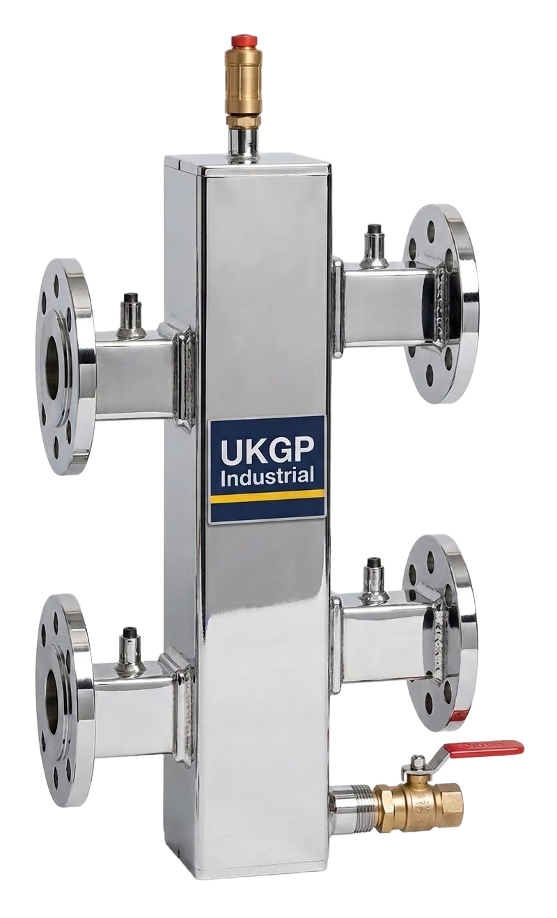
UKGP-LLH-06
£765
- Length
- 400 mm
- Body
- DN125
- Height
- 780 mm
- Flow
- 12.0 m³/h
- Power
- 280 kW
High Power · DN50 – DN150 (PN16)
10 barg @ 110°C · Flanged PN16
Carbon steel body, flanged PN16, with Flamco Flexvent AAV and DN25 drain valve.
| Size | Length | Body | Height | Flow | Power | Part code | Price | Buy |
|---|---|---|---|---|---|---|---|---|
| 340 mm | DN100 | 720 mm | 8.6 m³/h | 200 kW | UKGP-LLH-07 | £645 | ||
| 400 mm | DN125 | 820 mm | 13.3 m³/h | 310 kW | UKGP-LLH-08 | £815 | ||
| 440 mm | DN150 | 920 mm | 18.9 m³/h | 440 kW | UKGP-LLH-09 | £985 | ||
| 520 mm | DN200 | 1,080 mm | 34.0 m³/h | 790 kW | UKGP-LLH-10 | £1,390 | ||
| 600 mm | DN250 | 1,240 mm | 52.9 m³/h | 1,230 kW | UKGP-LLH-11 | £1,845 | ||
| 640 mm | DN250 | 1,320 mm | 63.6 m³/h | 1,480 kW | UKGP-LLH-12 | £2,150 |
UKGP-LLH-07
£645
- Length
- 340 mm
- Body
- DN100
- Height
- 720 mm
- Flow
- 8.6 m³/h
- Power
- 200 kW
UKGP-LLH-08
£815
- Length
- 400 mm
- Body
- DN125
- Height
- 820 mm
- Flow
- 13.3 m³/h
- Power
- 310 kW
UKGP-LLH-09
£985
- Length
- 440 mm
- Body
- DN150
- Height
- 920 mm
- Flow
- 18.9 m³/h
- Power
- 440 kW
UKGP-LLH-10
£1,390
- Length
- 520 mm
- Body
- DN200
- Height
- 1,080 mm
- Flow
- 34.0 m³/h
- Power
- 790 kW
UKGP-LLH-11
£1,845
- Length
- 600 mm
- Body
- DN250
- Height
- 1,240 mm
- Flow
- 52.9 m³/h
- Power
- 1,230 kW
UKGP-LLH-12
£2,150
- Length
- 640 mm
- Body
- DN250
- Height
- 1,320 mm
- Flow
- 63.6 m³/h
- Power
- 1,480 kW
High Power · Engineered to order
10 barg @ 110°C · Carbon or stainless steel
Larger systems, engineered to order. Flange type and number of connections to customer requirements.
| Size | Length | Body | Height | Flow | Power | Part code | Price | Buy |
|---|---|---|---|---|---|---|---|---|
| DN150 — 6" | 700 mm | DN300 | 1,400 mm | 73 m³/h | 1,700 kW | UKGP-LLH-13 | POA | Enquire |
| DN200 — 8" | 800 mm | DN350 | 1,560 mm | 90 m³/h | 2,100 kW | UKGP-LLH-14 | POA | Enquire |
| DN200 — 8" | 850 mm | DN400 | 1,680 mm | 120 m³/h | 2,800 kW | UKGP-LLH-15 | POA | Enquire |
| DN250 — 10" | 950 mm | DN450 | 1,840 mm | 150 m³/h | 3,500 kW | UKGP-LLH-16 | POA | Enquire |
| DN250 — 10" | 1,000 mm | DN500 | 1,960 mm | 193 m³/h | 4,500 kW | UKGP-LLH-17 | POA | Enquire |
| DN300 — 12" | 1,150 mm | DN600 | 2,240 mm | 279 m³/h | 6,500 kW | UKGP-LLH-18 | POA | Enquire |
| DN400 — 16" | 1,400 mm | DN750 | 2,720 mm | 451 m³/h | 10,500 kW | UKGP-LLH-19 | POA | Enquire |
| DN450 — 18" | 1,500 mm | DN800 | 2,900 mm | 516 m³/h | 12,000 kW | UKGP-LLH-20 | POA | Enquire |
| DN500 — 20" | 1,650 mm | DN900 | 3,200 mm | 667 m³/h | 15,500 kW | UKGP-LLH-21 | POA | Enquire |
| DN600 — 24" | 1,900 mm | DN1050 | 3,720 mm | 903 m³/h | 21,000 kW | UKGP-LLH-22 | POA | Enquire |
DN150 — 6" low loss header
UKGP-LLH-13
POA
- Length
- 700 mm
- Body
- DN300
- Height
- 1,400 mm
- Flow
- 73 m³/h
- Power
- 1,700 kW
DN200 — 8" low loss header
UKGP-LLH-14
POA
- Length
- 800 mm
- Body
- DN350
- Height
- 1,560 mm
- Flow
- 90 m³/h
- Power
- 2,100 kW
DN200 — 8" low loss header
UKGP-LLH-15
POA
- Length
- 850 mm
- Body
- DN400
- Height
- 1,680 mm
- Flow
- 120 m³/h
- Power
- 2,800 kW
DN250 — 10" low loss header
UKGP-LLH-16
POA
- Length
- 950 mm
- Body
- DN450
- Height
- 1,840 mm
- Flow
- 150 m³/h
- Power
- 3,500 kW
DN250 — 10" low loss header
UKGP-LLH-17
POA
- Length
- 1,000 mm
- Body
- DN500
- Height
- 1,960 mm
- Flow
- 193 m³/h
- Power
- 4,500 kW
DN300 — 12" low loss header
UKGP-LLH-18
POA
- Length
- 1,150 mm
- Body
- DN600
- Height
- 2,240 mm
- Flow
- 279 m³/h
- Power
- 6,500 kW
DN400 — 16" low loss header
UKGP-LLH-19
POA
- Length
- 1,400 mm
- Body
- DN750
- Height
- 2,720 mm
- Flow
- 451 m³/h
- Power
- 10,500 kW
DN450 — 18" low loss header
UKGP-LLH-20
POA
- Length
- 1,500 mm
- Body
- DN800
- Height
- 2,900 mm
- Flow
- 516 m³/h
- Power
- 12,000 kW
DN500 — 20" low loss header
UKGP-LLH-21
POA
- Length
- 1,650 mm
- Body
- DN900
- Height
- 3,200 mm
- Flow
- 667 m³/h
- Power
- 15,500 kW
DN600 — 24" low loss header
UKGP-LLH-22
POA
- Length
- 1,900 mm
- Body
- DN1050
- Height
- 3,720 mm
- Flow
- 903 m³/h
- Power
- 21,000 kW
Prices ex VAT. Insulation jackets, horizontal-header connection manifolds and stainless steel bodies available on request — call +44 20 8935 5572.
Variants
Low loss header — flanged & threaded configurations
Benefits
Why specify a UKGP low loss header
- Primary / secondary hydraulic separation
- Insulated and uninsulated options
- Integrated air vent and drain points
- Pre-fabricated to project specifications
Typical applications
Low loss header specifications
- Flow rate
- Up to 240 m³/h
- Pressure
- Up to 10 bar
- Connections
- Flanged or threaded
- Materials
- Carbon steel, stainless
Technical guide
What is a low loss header?
A low loss header (sometimes called a hydraulic separator or buffer header) is a vertical or horizontal vessel installed between the primary heat source circuit — typically the boilers or chillers — and the secondary distribution circuits that serve emitters, AHUs, calorifiers or underfloor heating. Its job is to hydraulically decouple the two sides so that the primary and secondary pumps cannot fight one another, regardless of how many circuits are running at any given moment.
The header is sized so that fluid velocity inside it falls to roughly 0.1 m/s. At that velocity, the pressure drop across the header is effectively zero, while entrained air rises to the top for venting and heavier dirt and magnetite settle at the base for blowdown.
Why hydraulic separation matters
In modern multi-boiler and variable-flow systems, each circuit has its own pump with its own duty curve. Without separation, the highest-pressure pump dominates: weaker secondary pumps are overpowered, modulating boilers see unstable return temperatures, and condensing efficiency collapses. A correctly sized low loss header gives every circuit an independent zero-pressure reference, so each pump operates at its true design duty.
How to size and install correctly
Match primary and secondary flow rates
Ideally the secondary flow should equal or slightly exceed the primary. If secondary flow is higher, hot return water mixes back into the secondary flow — boilers stay condensing and ΔT is preserved.
Size for ~0.1 m/s internal velocity
This keeps the pressure drop across the header negligible. Our calculator below applies this rule along with the standard 3× DN rule (header diameter ≈ 3× connection DN) used across UK plant rooms.
Allow 3× DN between tappings
Vertical pitch between primary flow, primary return, secondary flow and secondary return tappings should be at least three connection diameters apart to prevent short-circuiting and ensure clean separation.
Vent, drain and insulate
Always specify an automatic air vent at the top, a drain at the bottom and full insulation. A magnetic dirt pocket or downstream side-stream filter further protects boilers and plate exchangers.
Commission with pump speed control
On variable-speed primary pumps, control off return temperature or ΔT — not differential pressure across the header (which is near zero by design). Set secondary pumps to deliver the design flow at the index circuit.
Hydraulic balancing checklist
A low loss header only delivers its full benefit when the surrounding circuits are themselves balanced. Before commissioning:
- Calculate design flow for every secondary circuit from kW ÷ (1.16 × ΔT).
- Select each pump on the index circuit duty and verify the operating point sits left of the curve knee.
- Fit a double-regulating valve or PICV on every branch and proportionally balance to within ±10% of design flow.
- Confirm primary flow ≥ sum of running secondary flows under worst-case load.
- Record return temperatures at the header — primary return should track the lowest secondary return when boilers are condensing correctly.
Frequently asked questions
What's the difference between a low loss header and a buffer vessel?
A low loss header provides hydraulic separation but holds little stored energy. A buffer vessel adds thermal mass to reduce boiler short-cycling on low load. Many plant rooms specify both, or a combined buffer-header arrangement.
Vertical or horizontal orientation?
Vertical is preferred — it naturally separates air to the top and dirt to the bottom. Horizontal headers are used where headroom is tight, but lose the deaeration and de-sludging benefits.
Can a low loss header be used on chilled water?
Yes. The same separation principle applies; ensure full vapour-tight insulation, an automatic air vent and condensate management around the vessel.
Sizing tool
Low loss header sizing calculator
Quick indicative sizing for your project. For a formal selection and quotation our engineering team will validate the duty and confirm tappings.
Indicative sizing
Recommended header
Enter boiler output and ΔT to see your recommended header sizing.
Indicative only. Final selection considers fluid properties, layout constraints and full duty validation by UKGP Industrial engineering.
Get a formal quotation
Send these results to our engineers.
We’ll validate the sizing, confirm materials and connections, and respond with a fully detailed quotation — typically within one working day.
UK delivery
Stocked sizes — same-day dispatch from our UK warehouse for orders placed before 3pm (Mon–Fri)
4-year warranty
Manufacturer-backed defect cover on every UKGP product
Engineer support
Sizing, drawings & site advice — free
Call the team
+44 20 8935 5572 · 8am–5pm
Buying answers
Quick answers before you order
Can't see your question? Call +44 20 8935 5572 or email sales@ukgpindustrial.co.uk — our engineers respond inside one working day.
Latest guides
Latest low loss headers guides
What is low loss header technology in commercial HVAC?
Understanding what is low loss header equipment is essential for any modern commercial plant room design where multiple heat sources must serve varying load circuits. This critical component acts as a neutral point of pressure, ensuring hydraulic separation and protecting high-efficiency condensing boilers from variable flow rates and temperature fluctuations.
Read buyers guide · 10 minWhat is a low loss header on a heating system?
Understanding what is a low loss header on a heating system is fundamental for any building services consultant or M&E contractor aiming to deliver a reliable commercial plant room. This critical component acts as a bridge between the boiler circuit and the distribution circuit, ensuring hydraulic independence and protecting delicate heat sources from variable flow rates. By integrating a UKGP low loss header, engineers can harmonise primary and secondary circuits while significantly extending the operational lifespan of the installation.
Read buyers guide · 9 minWhat does a low loss header do for plant room efficiency?
When designing high-output commercial heating systems, engineers often ask exactly what does a low loss header do to maintain hydraulic stability between primary and secondary circuits. By decoupling the boiler loop from the variable demand of the building, these vessels ensure consistent flow rates and protect sensitive primary equipment from damage.
Read buyers guide · 9 minTechnical Guide to the WH40 Low Loss Header
The wh40 low loss header is a critical component for ensuring hydraulic separation between primary boiler circuits and secondary distribution loops in modern plant rooms. When properly specified, a wh40 low loss header prevents conflicting pump flows and ensures consistent delta-T management across various heat loads and boiler configurations.
Read buyers guide · 9 minSpecifying a Spirovent Low Loss Header for Modern Systems
Specifying a spirovent low loss header requires a deep understanding of hydraulic separation to ensure that variable flow primary circuits do not interfere with secondary heat emitters. When engineers integrate a spirovent low loss header into a commercial plant room, they are prioritising boiler protection and system efficiency by managing differential pressures across the heat source.
Read buyers guide · 10 minCommercial Guide to the Spirotherm Hydraulic Separator
Optimising hydronic systems requires precise hydraulic decoupling to ensure variable flow primary circuits interact correctly with constant flow or high-demand secondary circuits. Integrating a spirotherm hydraulic separator within your commercial heating design allows for effective air, dirt, and hydraulic management, preventing common issues like pump conflict and boiler short-cycling. UKGP Industrial provides the technical oversight and high-specification alternatives needed to ensure these components meet the rigorous demands of BSRIA BG29 and BG50 standards for water quality and system longevity.
Read