The Role of a Low Loss Header System in Hydraulic Separation
In modern commercial heating installations, achieving a balanced hydraulic state is critical for longevity and efficiency. A low loss header system acts as a neutral point of pressure, allowing the boiler's primary pump and the secondary system pumps to operate at their required flow rates without interfering with one another. This is particularly vital in systems where multiple boilers are cascaded or where the variable flow demand of the building fluctuates significantly throughout the day. By decoupling these circuits, engineers can ensure that the primary loop maintains the minimum flow rate required by leading commercial boiler manufacturers, preventing nuisance tripping and heat exchanger stress.
Without a properly sized low loss header system, the secondary pumps can exert a 'pulling' effect on the primary circuit, potentially exceeding the boiler's design parameters. Conversely, if the primary pump is significantly more powerful than the secondary demand, it may force hot water through the bypass or cause overheating in stagnant zones. This hydraulic independence is also a key factor in complying with BSRIA BG50 guidelines regarding water quality and system management. By providing a low-velocity zone, the header allows for better control of the system bypass, ensuring that return temperatures stay within the condensed mode range for high-efficiency condensing boilers.
For M&E contractors and consultants, the low loss header system represents a insurance policy against the unpredictable nature of complex secondary pipework. Whether the project involves fan coil units, underfloor heating, or high-temperature radiator circuits, the header provides a common point of reference. This approach reduces the complexity of pump sizing during the design phase, as the head loss calculation for the primary circuit is simplified to the boiler and the header itself. Properly specified, these components are essential for maintaining the operational window of the plant room, facilitating a smoother commissioning process and lower long-term maintenance costs for FM teams.
- Decouples primary boiler circuits from secondary distribution zones.
- Maintains manufacturer-recommended flow rates in the primary loop.
- Reduces mechanical stress on commercial pump sets and heat exchangers.
- Provides a neutral pressure zone for stable hydraulic balancing.
Technical Configuration and BSRIA Compliance
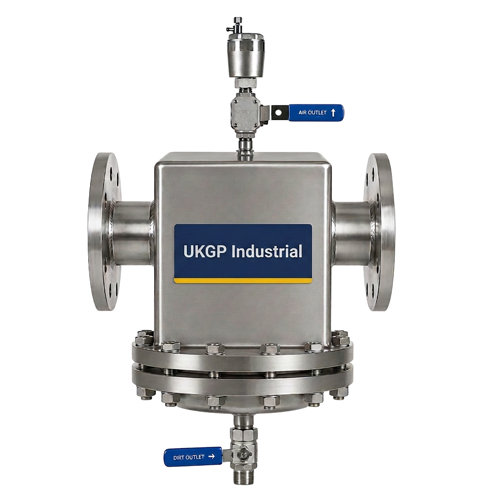
Adhering to industry standards such as BSRIA BG29 and BG50 is paramount when integrating a low loss header system into a plant room. These documents emphasize the importance of air removal and dirt management, functions that are inherently supported by the low-velocity environment within a large-diameter header. As the water enters the header, the reduction in velocity allows suspended solids to settle at the bottom and entrained air to rise to the top. This makes the header a primary location for installing automatic air vents and drain valves. Ensuring that the low loss header system is scaled relative to the maximum power output, typically ranging from 40 kW to 2000 kW in commercial settings, is the first step toward a compliant installation.
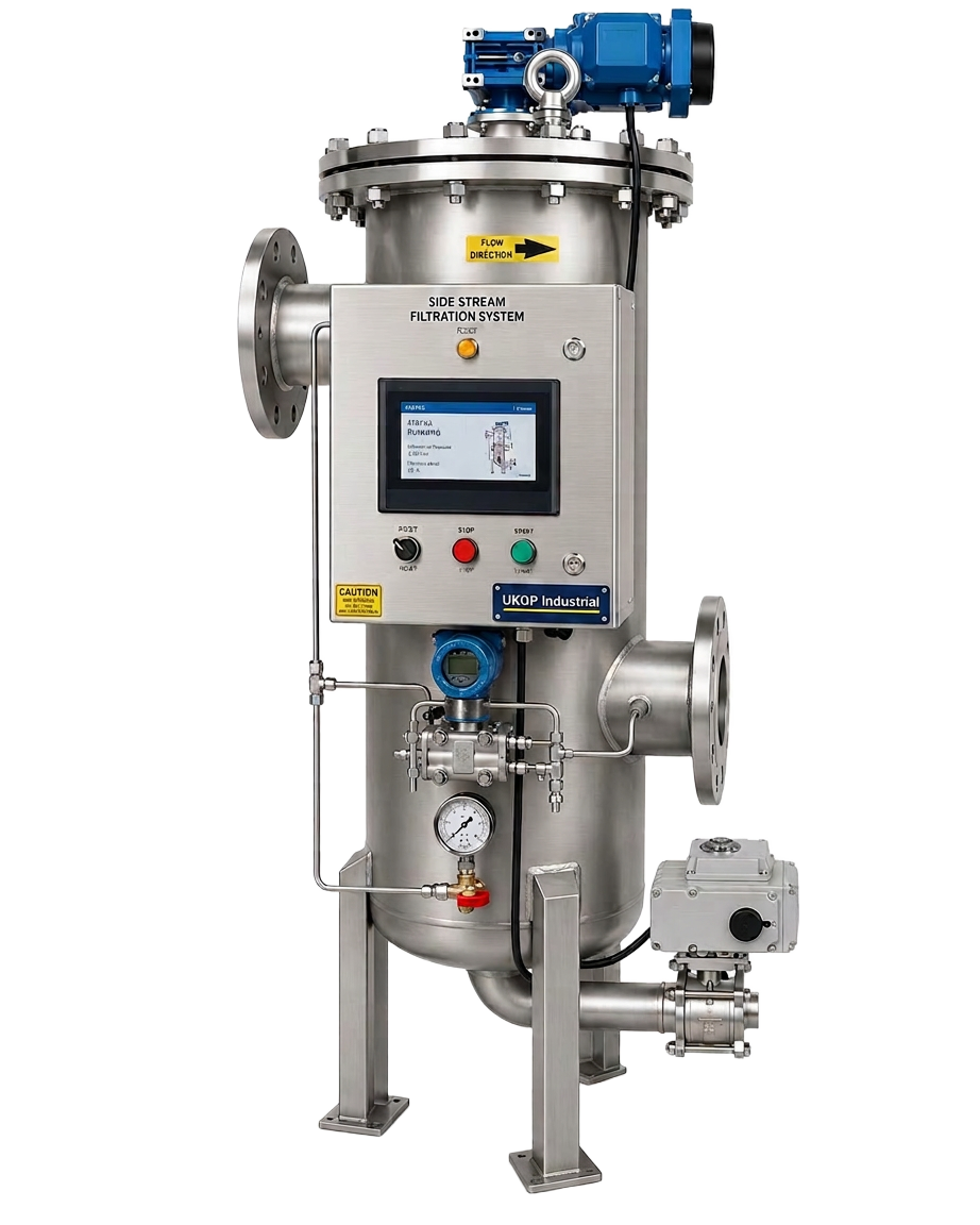
When consulting BS 8552 for water sampling, the header often serves as a strategic point for monitoring system health. However, the header alone is rarely sufficient for full system protection. To meet the rigorous debris removal requirements of BSRIA BG29, British engineers frequently pair the header with dedicated filtration technologies. For example, installing side-stream filtration alongside our hydraulic separation equipment ensures that magnetite and fine particles are continuously removed from the secondary loop. This combined approach protects sensitive components like control valves and energy meters, which are prone to failure in dirty water conditions, thus extending the life of the entire HVAC asset.
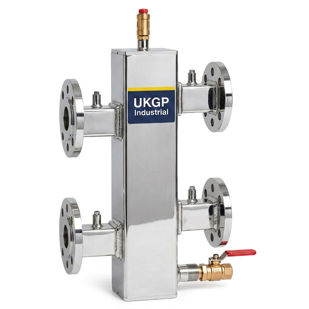
The physical construction of the header must also consider thermal losses to meet modern energy efficiency standards. A high-quality low loss header system should be supplied with a tailored insulation jacket to minimize heat dissipation into the plant room environment. This is especially important in high-capacity systems where the surface area of the vessel is significant. Our range of headers, available in flanged PN16 or threaded BSP connections, are designed to integrate seamlessly into BSRIA-compliant schemes. We offer units with a 2-year warranty and lead times of 2-3 weeks, ensuring that procurement leads can stay on schedule during tight refurbishment or new-build windows.
- Enhances compliance with BSRIA BG29 and BG50 maintenance standards.
- Acts as a secondary point for de-aeration and dirt collection.
- Reduces convective heat loss when used with fitted insulation jackets.
- Supports BS 8552 water quality monitoring protocols.
Selecting the Right Header for 40-2000 kW Applications
Sizing a low loss header system is a critical task that depends on the total system flow rate rather than just the boiler capacity. The fundamental principle is that the water velocity within the header should not exceed 0.5 metres per second to allow for effective hydraulic decoupling and some degree of air/dirt separation. For commercial applications ranging from 40 kW to 2000 kW, the internal diameter of the vessel must be carefully calculated. A header that is too small will fail to provide the quiet, neutral zone required, potentially leading to turbulent flow and pump cavitation. Conversely, an oversized header adds unnecessary cost and physical footprint to the plant room, which is often at a premium.
UKGP Industrial provides a comprehensive range of low loss headers to suit various installation requirements. For smaller commercial projects, threaded BSP connections offer ease of installation and speed. For larger industrial or district heating schemes, flanged PN16 connections provide the robust, leak-free jointing required for high-pressure environments. Our units are manufactured to high standards, ensuring they can withstand the rigours of continuous operation in demanding environments. When requesting a quote, specify your peak flow rates and connection preferences to ensure the low loss header system provided matches the unique hydraulic profile of your specific secondary circuits.
Integration of the header into the plant room layout should also consider the orientation and height. Vertical headers are the industry standard, facilitating the natural collection of air at the highest point and sediment at the lowest. By incorporating a UKGP low loss header, engineers can be confident in a 2-year warranty and a product that is designed for longevity. With a lead time of just 2-3 weeks, our commercial headers are an ideal solution for contractors looking for high-spec UK-supplied components. Whether you are managing a decentralised boiler house or a concentrated plant room, the right header choice will directly impact the reliability of the building's thermal comfort.
- Optimised for flow rates across the 40 kW to 2000 kW power range.
- Available in both BSP threaded and PN16 flanged configurations.
- Compact designs available to suit restricted plant room footprints.
- Fully jacketed options to ensure compliance with Part L insulation requirements.
Protecting the Low Loss Header System from Corrosion
While a low loss header system facilitates hydraulic efficiency, its internal surfaces and the wider circuit are still vulnerable to corrosion and scale without proper chemical management. Oxygen ingress and the presence of mixed metals in a commercial circuit create an environment ripe for magnetite formation. To mitigate this risk, dosing pots should be used to introduce corrosion inhibitors and biocides into the system bypass. Keeping the water chemistry within the parameters of BG50 prevents the accumulation of sludge within the header, which could otherwise restrict flow and erode the internal baffles over time.
Regular monitoring of pH levels and inhibitor concentrations is essential to maintain the integrity of the hydraulic separator. In high-value plant rooms, installing pH sensors and transmitters provides real-time data on water conditions, allowing FM teams to react before corrosion starts to damage the low loss header system or the primary heat exchangers. This proactive approach is particularly important in systems that incorporate both stainless steel and copper components, where galvanic corrosion is a constant threat. Maintaining a stable chemical environment ensures that the 2-year warranty on your plant room hardware remains valid and that the system performs at peak efficiency.
Beyond chemical dosing, physical air and dirt separation units can be installed upstream of the header to further protect the primary circuit. While the header provides some separation, dedicated units are more effective at removing micro-bubbles and fine non-magnetic particles. By combining a UKGP low loss header system with advanced separation and dosing tools, contractors can offer clients a 'best-in-class' solution that minimizes downtime and repair costs. If you are currently designing a commercial heating scheme, get in touch with our technical team to discuss how our BSP and PN16 headers can be integrated into your water treatment strategy.
- Integrate dosing pots for consistent chemical water treatment.
- Utilise pH sensors to monitor real-time corrosive potential.
- Ensure system longevity by preventing magnetite buildup in the header.
- Follow BG50 guidelines for chemical cleaning and maintenance.
Improving Temperature Control and Boiler Longevity
The primary advantage for FMs and plant room engineers using a low loss header system is the significant improvement in boiler cycle times. In systems without a header, boilers often cycle frequently due to rapid changes in secondary flow demand, leading to mechanical wear and high gas consumption. The header provides a volume of water that acts as a thermal buffer, smoothing out the 'spikes' in demand. This allows the boiler to modulate more effectively, running for longer periods at lower, more efficient firing rates. For major UK commercial boiler OEMs, maintaining these stable operating conditions is often a prerequisite for performance guarantees.
Temperature accuracy is also enhanced by a low loss header system. By providing a dedicated location for temperature sensors in the header, the building management system (BMS) can accurately measure the mixed flow temperature reaching the secondary circuits. This data allows the BMS to adjust the primary boiler output more precisely, ensuring that the target flow temperature is met without overshooting. For contractors, this means fewer call-backs related to temperature fluctuations or 'no heat' reports in distant parts of the building. The result is a more resilient heating network that meets the CIBSE comfort standards for occupants.
Finally, the hydraulic separation provided by the header protects the primary heat exchangers from the thermal shock associated with sudden cold water return. This is particularly relevant in older buildings with large radiator volumes or systems with high-mass secondary pipework. By allowing a degree of bypass and mixing within the low loss header system, the return water temperature is tempered before it reaches the boiler. This thermal stability is crucial for ensuring that the investment in high-efficiency boilers pays off over their expected 15-to-25-year service life. Our UK-manufactured headers are the reliable choice for ensuring this critical separation in any 40-2000 kW commercial application.
- Reduces boiler cycling and associated mechanical component wear.
- Enables precise BMS monitoring at the point of hydraulic mixing.
- Protects heat exchangers from thermal shock during cold starts.
- Improves overall seasonal efficiency of the heating plant.
Installation Best Practices for Commercial Headers
When installing a low loss header system, spatial orientation and accessibility for maintenance are key considerations. The header should be positioned vertically to utilize its natural de-aeration properties, with an automatic air vent installed at the top-most tapping. Sufficient clearance must be provided at the bottom for a drain valve, allowing for the periodic flushing of any sludge that has settled in the vessel. In tight plant rooms common in Surrey and London, the compact footprint of our headers—available in both flanged and threaded options—facilitates easier integration without compromising on the 0.5 m/s velocity rule.
Correct pipework alignment is also essential to prevent mechanical stress on the header's connections. Whether using PN16 flanges or BSP threads, the pipework should be independently supported so that the weight is not carried by the header itself. In many large-scale commercial installs, the use of expansion bellows is recommended on the primary and secondary connections to absorb thermal expansion and vibration. This prevents the transfer of stresses into the low loss header system, protecting the integrity of the welded joints and the insulation jacket. Our units are built to last, but correct installation practice remains the foundation of a 2-year-warranty-worthy system.
Commissioning the header involves balancing the flow rates on both the primary and secondary sides. Engineers should verify that the flow from the boiler side matches the design specification while the secondary pumps are adjusted to meet the building's heat load. A well-installed low loss header system will show a minimal temperature difference across the header during normal operation, indicating balanced flow. With lead times of just 2-3 weeks, UKGP Industrial ensures that your site team has the necessary components to complete the hydraulic circuit on time and to the highest professional standard. Contact us today for technical specifications and lead-time confirmation.
- Orient headers vertically for effective air and dirt separation.
- Use independent pipe supports to avoid stressing connections.
- Install expansion bellows to manage thermal movement in large loops.
- Verify balancing during commissioning to ensure hydraulic neutrality.
Frequently asked questions
What is the primary function of a low loss header system?
- Its main function is to decouple the primary boiler circuit from the secondary heating circuits, allowing each to operate at its own flow rate and pressure without interfering with the other. This ensures hydraulic stability and protects boilers from incorrect flow conditions.
Can a low loss header replace an air and dirt separator?
- While a header provides some air and dirt separation due to reduced water velocity, it is generally recommended to use dedicated air and dirt separators for full system protection, especially in dirty or older heating networks to meet BSRIA BG29 standards.
What connection types are available for UKGP low loss headers?
- We offer both BSP threaded connections for smaller applications and PN16 flanged connections for larger commercial and industrial systems, covering a power range from 40 kW up to 2000 kW.
How does a low loss header improve boiler efficiency?
- By acting as a thermal buffer and ensuring hydraulic separation, it reduces boiler short-cycling. This allows the boiler to run for longer, more efficient periods, reducing fuel consumption and wear on internal components.
Are insulation jackets included with the headers?
- Yes, our low loss headers are supplied with fitted insulation jackets to minimise heat loss and improve the overall efficiency of the plant room, in line with modern energy regulations.