The Fundamentals of Low Loss Header Pump Position
In modern commercial heating systems, particularly those utilising multiple high-efficiency boilers, achieving hydraulic decoupling is essential. The low loss header pump position is the cornerstone of this design, as it dictates where the pressure differential is neutralised. Primary pumps are typically located on the return line to the boiler to ensure they are handling cooler water and maintaining positive pressure, while secondary pumps are placed on the flow side of the header. Confusing these positions can lead to the 'fighting' of pumps, where the primary and secondary circuits attempt to pull or push water against each other, drastically reducing the lifespan of the equipment and increasing energy consumption. By adhering to the correct low loss header pump position, engineers ensure the header acts as a point of zero pressure, allowing each circuit to operate independently based on its specific demand profile.
Failure to observe the correct low loss header pump position often results in poor temperature control and hydraulic short-circuiting. When a pump is incorrectly positioned relative to the neutral zone, it can bypass the boiler loop entirely or cause excessive flow velocity through the header, which renders the air and dirt separation functions of the vessel ineffective. CIBSE guidelines suggest that the velocity within the header should be kept below 0.5 metres per second to allow for effective hydraulic separation. A correctly identified low loss header pump position facilitates this by ensuring that the primary and secondary flow rates remain distinct. When designing for larger commercial loads from 40 kW up to 2000 kW, the precision of this installation becomes even more vital to prevent thermal shock in high-output boilers and to protect the integrity of the heat exchanger surfaces throughout the building's lifespan.
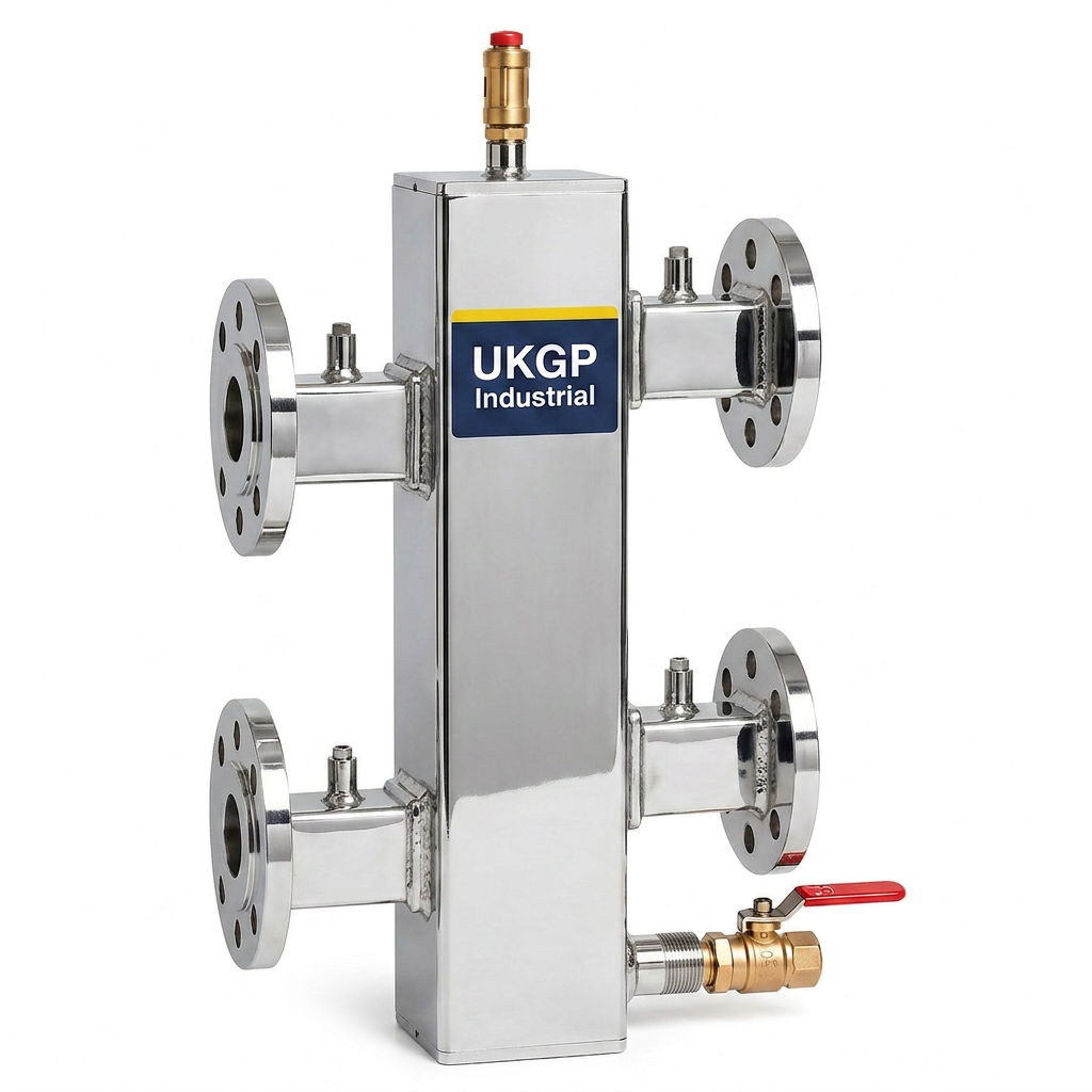
Correctly mapping out the low loss header pump position during the initial design phase reduces the need for costly troubleshooting during commissioning. M&E contractors must ensure that the secondary pumps are never pulling water directly from the primary loop without the buffer of the header. This separation allows for variable speed pumps on the secondary side to ramp up or down based on zone demand without affecting the minimum flow requirements of the primary boiler circuit. British Standards and BSRIA recommendations focus on this independence to prevent the circulating pumps from exceeding their design parameters. Integrating a high-quality UKGP low loss header, which features a 2-year warranty and high-grade insulation jacket, ensures that once the low loss header pump position is established, the system maintains its thermal efficiency with minimal heat loss and complete hydraulic stability over the long term.
- Maintain primary pumps on the return for lower operating temperatures
- Keep secondary pumps on the flow side to push to the load
- Ensure the neutral point is clearly identified between the two circuits
- Monitor velocity within the header to stay below 0.5m/s
Hydraulic Separation and Pressure Neutrality
The physics of hydraulic separation relies on the low loss header pump position being situated such that the header represents a zone of negligible pressure drop. This allows the primary and secondary circuits to be hydraulically decoupled, meaning the flow rate in one circuit does not affect the flow rate in the other. In a typical UK commercial installation, the primary circuit is designed for a constant flow to protect the boiler, while the secondary circuit uses variable speed drives to respond to building load. If the low loss header pump position is incorrect, the pressure differential created by the larger secondary pumps can 'pull' water through the primary circuit, potentially exceeding the boiler's maximum flow rate and causing error codes or mechanical damage. This is why the header acts as a bridge, where the low velocity is the key to maintaining control over the system hydraulics.
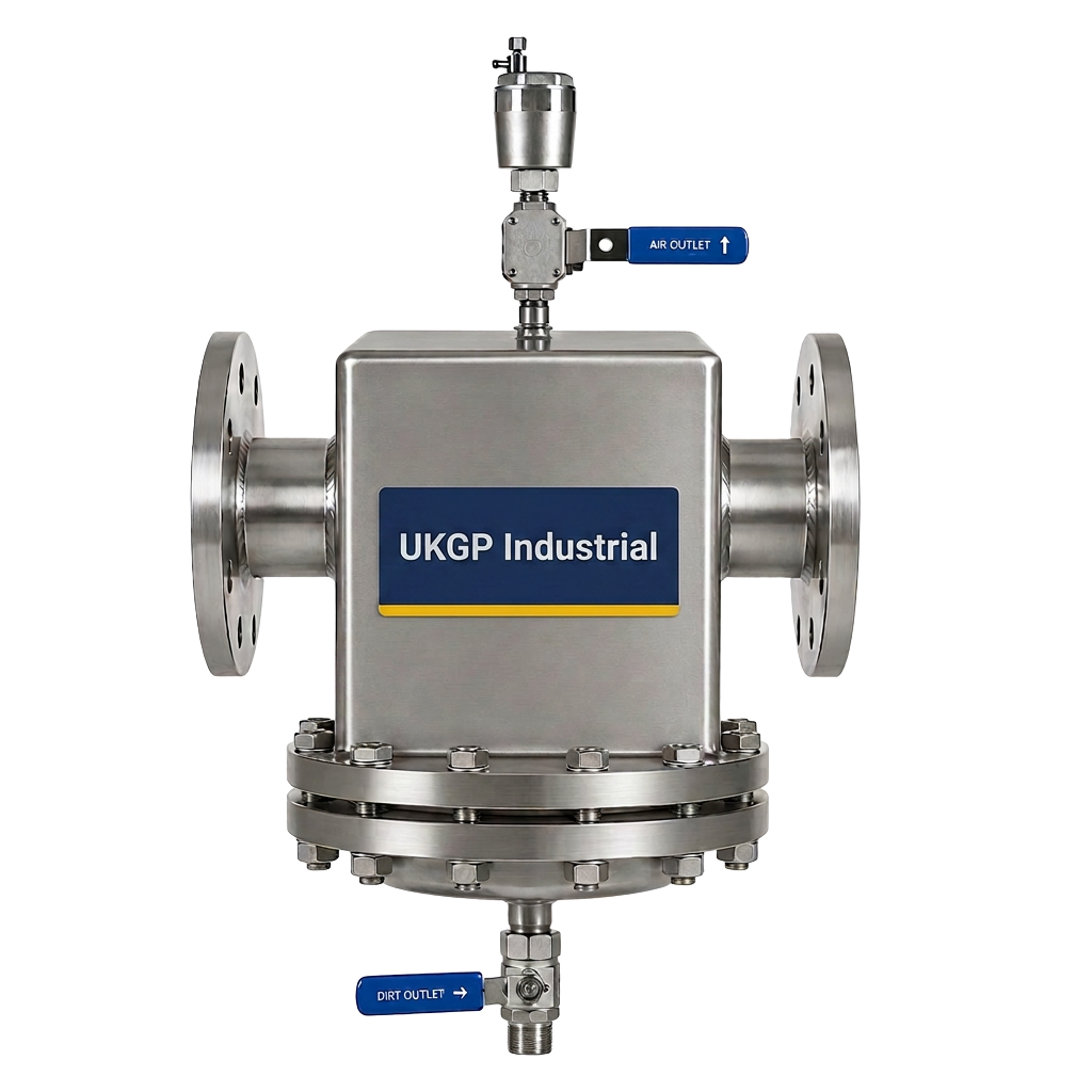
According to BSRIA BG29 and BG50, water quality and hydraulic balance are inextricably linked. An incorrect low loss header pump position can lead to turbulence, which re-suspends settled solids and introduces air back into the system. While a separate air and dirt separator is often used, the low loss header also performs a secondary role in air venting. If the pumps are positioned such that they create high-velocity bypasses, the dwell time required for particles to settle is lost. Commercial building service consultants often specify UKGP headers because they are designed to accommodate these flow dynamics, with sizes ranging from 40 kW to 2000 kW and available in both BSP and PN16 flanged options. Ensuring the low loss header pump position aligns with the internal baffle design of these units is essential for long-term operational excellence and system longevity.
When dealing with varying flow rates, the low loss header pump position ensures that the temperature of the water delivered to the secondary circuit remains stable. For instance, if the secondary demand exceeds the primary supply, the header allows return water to mix with the flow, preventing the 'starvation' of the pumps. Conversely, if the primary flow is higher than the demand, the excess flow bypasses through the header back to the boiler. This flexibility is only possible if the pumps are situated correctly relative to the header. Many plant-room engineers find that standardising the low loss header pump position across all projects leads to fewer call-outs and more predictable system performance. By selecting a UKGP unit with a 2-3 week lead time, contractors can ensure they have the right hardware ready for precise installation as per these hydraulic rules.
- Primary circuit flow must meet boiler minimum requirements
- Secondary circuit flow handles variable thermal loads
- Header serves as a bypass during low demand periods
- Proper pump location prevents pump 'fighting' or series operation
Commissioning Best Practices for Pump Integration
Commissioning a system after verifying the low loss header pump position requires careful measurement of flow rates and differential pressures. Engineers should use the commissioning valves typically installed alongside the secondary pumps to balance the system while the primary circuit is running. If the low loss header pump position has been correctly implemented, adjusting the secondary flow will have no measurable impact on the flow across the boiler. This is the ultimate test of hydraulic decoupling. BSRIA BG29 provides the framework for these pre-commissioning cleaning and flushing procedures, but the mechanical setup must be sound for the chemical treatment to be effective. A UKGP dosing pot can be used in conjunction with the header to introduce the necessary inhibitors once the hydraulic balance is confirmed.
Temperature sensors should be placed strategically to monitor the performance of the chosen low loss header pump position. Sensors on the primary flow, primary return, secondary flow, and secondary return allow for the calculation of the mixing ratio within the header. This data is vital for Building Management Systems (BMS) to modulate boiler firing rates and pump speeds efficiently. If the low loss header pump position is flawed, the temperature sensors may provide erratic readings due to turbulent mixing or back-flow within the vessel. Commercial FM managers often prefer UKGP low loss headers because their robust construction and supplied insulation jackets simplify the integration of these control sensors, ensuring that the plant room operates at peak efficiency from the moment of handover through the two-year warranty period and beyond.
Finally, the bypass characteristics of the header must be considered. In systems where the low loss header pump position is on the flow side for secondary heating, the header must be sized to handle the maximum possible combined flow without creating significant resistance. This involves selecting the correct diameter for the BSP or PN16 flanged connections. UKGP offers customisable options for headers to suit specific site requirements, ensuring that the physical layout of the plant room does not force a compromise on the low loss header pump position. With lead times of just 2-3 weeks, even fast-track refurbishments can benefit from a correctly sized and positioned header that complies with all relevant British Standards, including BS EN 14917 where expansion bellows are used to mitigate thermal stresses in the pipework connected to the header.
- Verify decoupling by measuring primary flow during secondary modulation
- Integrate BMS sensors to monitor return water temperatures
- Observe BSRIA BG29 for system cleanliness prior to pump activation
- Utilise UKGP dosing pots for chemical treatment post-balancing
Managing Thermal Expansion and System Integrity
In large-scale commercial plants, the heat generated can cause significant thermal expansion in the pipework connecting to the low loss header. While the low loss header pump position is vital for hydraulics, the mechanical layout must also account for expansion and contraction to prevent stress on the pump flanges. BS EN 14917 provides standards for expansion bellows which are often required in these high-output 40-2000 kW systems. If the pump is bolted directly to a rigid header without flexibility, the thermal movement can lead to seal failures or pump misalignment. Therefore, the low loss header pump position should be planned with enough clearance for these components to ensure the system remains leak-free and easy to maintain over its operational life.
Maintenance remains a top priority for facilities managers. A correctly established low loss header pump position allows for individual components to be isolated and serviced without draining the entire system. When the header is installed with high-quality valves and the pump is positioned on the secondary flow, technicians can easily swap out a failed pump whilst the primary boilers remain protected. UKGP headers come with a high-grade insulation jacket as standard, which not only prevents energy loss but can be easily removed and refitted during maintenance intervals. This practical design consideration, paired with the 2-year warranty, provides procurement leads with the confidence that they are investing in a system that respects both engineering principles and long-term serviceability requirements.
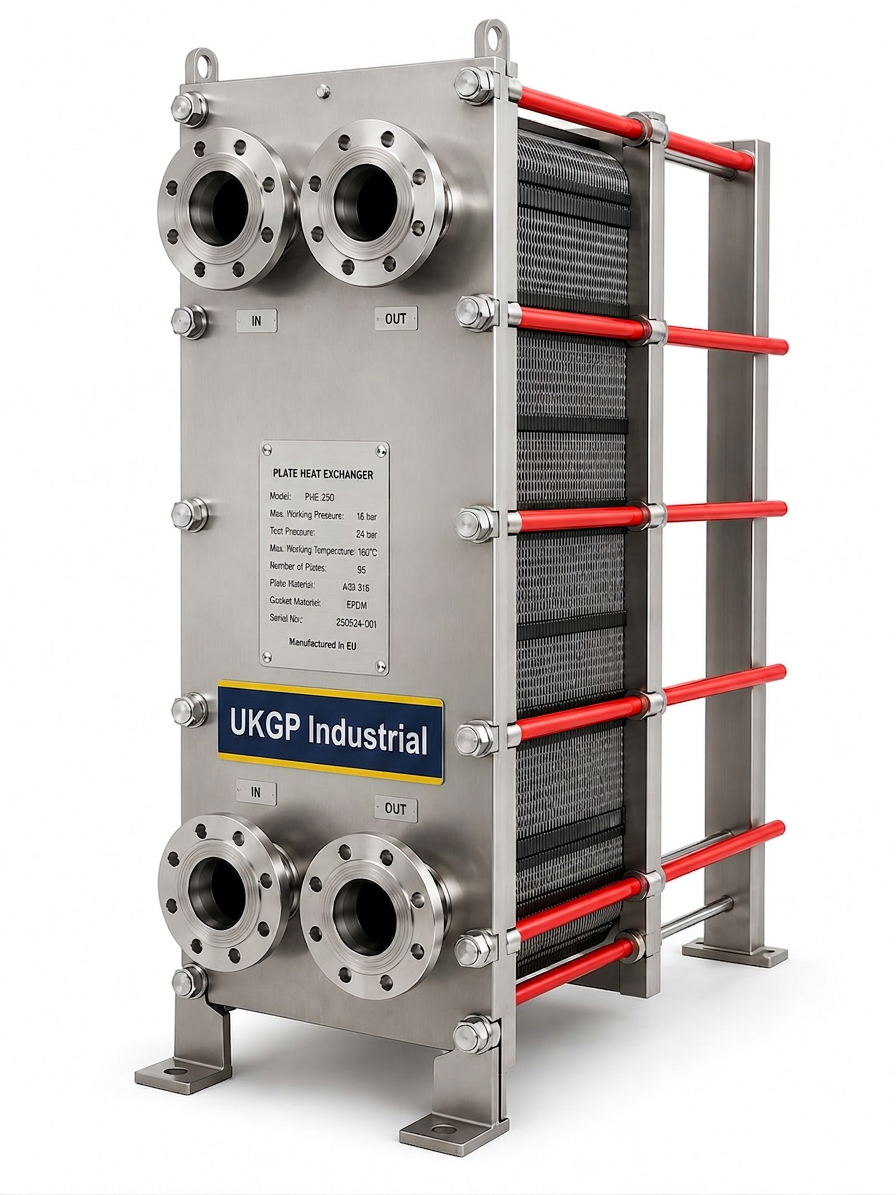
For complex multi-load systems involving underfloor heating, radiators, and domestic hot water (DHW) via a plate heat exchanger, the low loss header pump position becomes even more nuanced. Each secondary sub-circuit will have its own pump, and all must be positioned to draw from the header rather than the main distribution pipe to maintain individual zone control. This hierarchical approach to pump positioning ensures that the larger primary pumps only have to overcome the resistance of the boiler and the header itself. By sourcing a UKGP low loss header, contractors can obtain a unit that is perfectly matched to these multi-pumping requirements, ensuring that the transition from a 2000 kW boiler plant to various building loads is handled with professional-grade hydraulic precision.
- Incorporate expansion bellows to manage thermal stress
- Ensure insulation jackets are used to maintain system efficiency
- Size headers correctly for secondary sub-circuit pumping requirements
- Account for pump flange alignment to prevent premature mechanical wear
Sizing and Selection Rules for UK Plant Rooms
Selecting the correct vessel size is just as important as the low loss header pump position. A header that is too small will increase water velocity, causing the circuits to couple hydraulically and defeating the purpose of the installation. UKGP offers a range of headers from 40 kW to 2000 kW, ensuring that whether you are working on a small office block or a large industrial site, there is a unit with the correct volumetric capacity. The rule of thumb is to size the header based on the maximum flow rate of the primary circuit or the total flow rate of the secondary circuits, whichever is greater. This sizing ensures that the low loss header pump position remains effective even during peak demand periods when the system is running at full capacity.
Mechanical and electrical contractors often face tight deadlines, which is why UKGP’s 2-3 week lead time is a significant advantage. When the low loss header pump position is specified in the design, waiting months for a custom-built header can derail a project. By offering both threaded BSP and flanged PN16 options, UKGP ensures that the header can be integrated into the existing pipework without the need for extensive onsite modifications. The inclusion of a 2-year warranty further bolsters the case for these units in high-spec commercial tenders where reliability is non-negotiable. Using a purpose-built header rather than a site-fabricated alternative ensures that the internal flow characteristics are optimised for the intended pump positions.
The impact of the low loss header pump position on the air and dirt separation capabilities cannot be overstated. When water enters the larger volume of the header, its velocity drops, allowing air bubbles to rise and dirt to sink. If the pumps are positioned too close to the header inlets or outlets, they can create localized high-velocity zones that 'carry' these contaminants through the system. This can damage sensitive components like pH sensors and transmitters used for water quality monitoring. By following the standard install rules for the low loss header pump position, you allow the header to function as a multi-purpose vessel, improving both the hydraulic and chemical health of the heating system, which is a key requirement under British Standards for commercial plant maintenance.
- Match header kW rating to the total system load (up to 2000 kW)
- Select BSP or PN16 connections based on system pressure requirements
- Leverage 2-3 week lead times for time-sensitive UK projects
- Ensure 2-year warranty coverage is included in procurement specs
Final Checklist for Proper Header Installation
To conclude, the low loss header pump position is the defining factor in the success of a decoupled heating system. Contractors must verify that the primary pumps are pushing through the boiler and into the header, while secondary pumps draw water from the flow side of the header to distribute throughout the building. This setup maintains the independence of each circuit, protecting the boilers from low flow and the secondary zones from insufficient heat. Before signing off on an installation, engineers should refer back to CIBSE guides and ensure that all low loss header pump position rules have been followed, including the provision of sufficient straight pipe runs before and after the pumps to prevent turbulent flow into the header connections.
Requesting a quote for a UKGP low loss header is the first step toward ensuring these engineering rules are met with high-quality hardware. With units covering 40 kW to 2000 kW and features like integrated insulation and a 2-year warranty, UKGP provides the reliability required for prestigious UK commercial projects. The flexibility of flanged versions for large-bore pipework and threaded BSP versions for smaller installs allows for a perfect fit every time. By prioritising the low loss header pump position and using the right equipment, M&E contractors can deliver systems that are easier to balance, more efficient to run, and simpler to maintain over decades of building use.
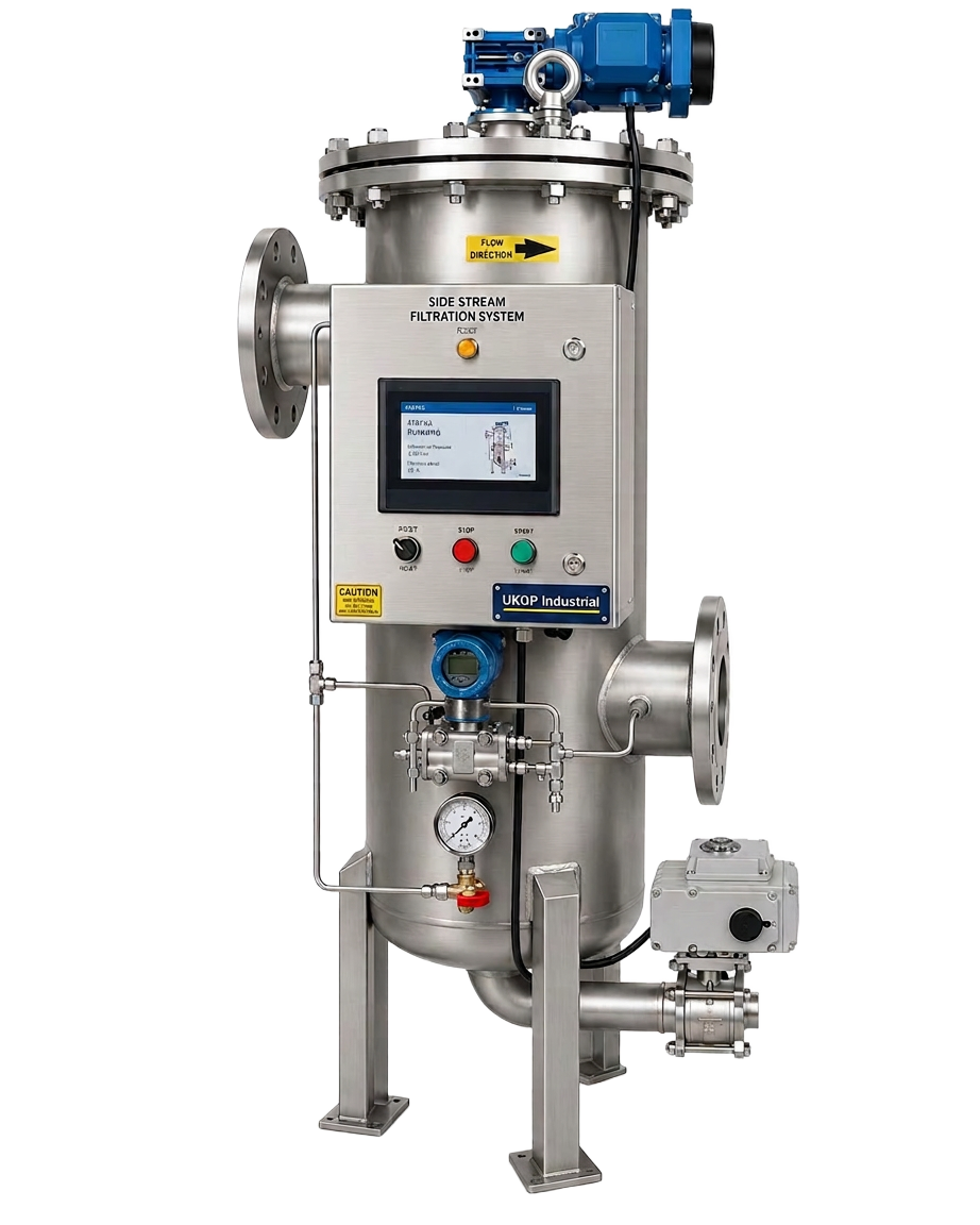
Properly documenting the low loss header pump position in the O&M manuals is the final step in a professional delivery. This ensures that future maintenance teams understand the hydraulic design and do not inadvertently alter the system in a way that causes coupling. Whether you are dealing with side stream filtration, chemical dosing, or primary boiler loops, the header remains the heart of the plant room. By sticking to the established rules and utilizing UKGP’s expertise and rapid delivery, you ensure every project meets the highest standards of British engineering. For your next plant room upgrade or new build, ensure the low loss header pump position is at the top of your technical checklist to guarantee a high-performing, BSRIA-compliant heating system.
- Include low loss header pump position in O&M documentation
- Choose UKGP for reliable 2-3 week delivery and support
- Cross-reference all installs with BS and CIBSE standards
- Verify insulation jacket fitment to maximize energy savings
Frequently asked questions
Where is the best low loss header pump position for a primary circuit?
- The primary pump should ideally be positioned on the return leg of the boiler circuit, pumping toward the boiler. This ensures the pump handles cooler water and maintains the primary loop's minimum flow requirements regardless of secondary demand.
Do I need a pump on both sides of a low loss header?
- Yes, for the system to function correctly and remain decoupled, you must have a primary pump to serve the boiler loop and separate secondary pumps for each distribution circuit, following the correct low loss header pump position rules.
Can a low loss header be used for cooling systems?
- Absolutely. While commonly used in heating, the same low loss header pump position rules apply to chilled water systems to separate the constant flow through the chiller from variable flow in the air handling units.
What is the lead time for a UKGP commercial low loss header?
- UKGP provides a lead time of 2-3 weeks for commercial low loss headers ranging from 40 kW to 2000 kW, ensuring your project stays on schedule with high-quality, flanged or threaded units.
What standards govern the installation of pumps and headers?
- Installations should follow CIBSE Guide B for hydraulics, BSRIA BG29 and BG50 for water quality and commissioning, and BS EN 14917 if expansion bellows are required for thermal management.