The Role of a Low Loss Header Manifold in Modern HVAC
In contemporary UK commercial HVAC design, the low loss header manifold serves as the thermal and hydraulic bridge between the primary heat source and the various secondary load circuits. This component is essential for maintaining independent flow rates, particularly when high-efficiency condensing boilers are utilised. Without proper hydraulic decoupling, the interaction between different pump speeds can lead to erratic pressure fluctuations, causing significant wear on commercial pump sets and potentially invalidating manufacturer warranties on heat exchangers. By incorporating a low loss header manifold, engineers can ensure that the primary circuit maintains a consistent flow rate while secondary circuits modulate based on real-time demand from BMS signals or thermostatic controls.
From a commercial perspective, ignoring the hydraulic integrity provided by a low loss header manifold often leads to increased operational costs and frequent call-outs for unbalanced systems. When the primary boiler pump and secondary distribution pumps are in series without separation, they can fight against each other, leading to cavitation and insufficient heat delivery to distal zones. Using this manifold arrangement ensures that the pressure drop across the bridge is negligible, hence the term 'low loss'. This design philosophy is supported by BSRIA recommendations, which advocate for stable primary flow to protect the longevity of the heat source and to allow for accurate temperature control across multiple distribution manifolds.
UKGP Industrial provides high-performance solutions for these challenges, offering units designed for 40-2000 kW outputs. These headers are available in both flanged PN16 and threaded BSP configurations, ensuring they meet the specific pipework requirements of any commercial plant room retrofit or new build. Each unit comes with a 2-year warranty and a high-quality insulation jacket to minimise heat loss into the plant room environment. With a lead time of just 2-3 weeks, these headers are an excellent choice for contractors looking to maintain project timelines while adhering to strict technical specifications for hydraulic separation and system balance.
- Eliminates hydraulic interference between primary and secondary pumps.
- Protects heat exchangers from variable flow stresses.
- Facilitates easier debris and air removal when correctly positioned.
- Essential for systems with multiple boiler cascades or mixed temperature zones.
Technical Sizing Considerations for Hydraulic Decouplers
Sizing a low loss header manifold is not merely about matching pipe diameters; it requires a precise calculation of the maximum possible flow rate across all integrated circuits. The header must be sized so that the internal velocity remains low enough to allow for hydraulic decoupling, typically aiming for a velocity below 0.5 metres per second within the vessel chamber. If the velocity is too high, the header fails to act as a point of zero pressure, and dynamic pressure from one circuit will inevitably impact the others. This often leads to cold spots in the building or boilers locking out due to high-temperature return water that hasn't properly mixed within the vessel volume.
Engineers must calculate the total heat load in kilowatts and convert this to a mass flow rate using the formula Q = m x Cp x ΔT. In modern systems, a ΔT of 20K is common for condensing efficiency, but many legacy systems operate on a 11K or 7K differential. The low loss header manifold must be robust enough to handle the largest flow rate calculated from either the primary or secondary side. UKGP Industrial offers units ranging from DN50 to DN300, ensuring matches for systems from 40 kW small commercial units up to 2000 kW industrial cascades. Ensuring the header is not undersized is the single most important factor in preventing turbulence and ensuring laminar flow transitions within the decoupling zone.
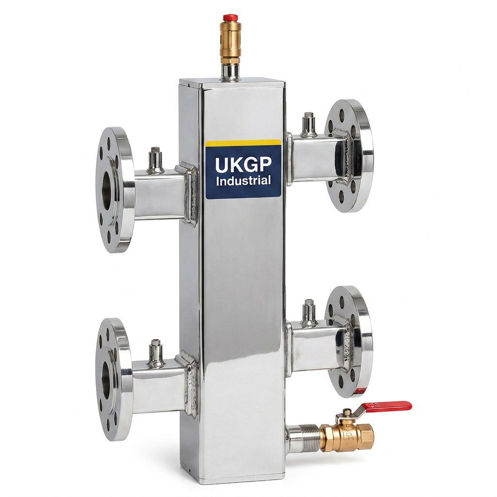
Furthermore, the physical orientation of the low loss header manifold plays a role in its effectiveness. Vertical headers are generally preferred as they naturally facilitate air separation at the top and dirt collection at the bottom. While dedicated units are used for separation, a well-sized manifold can assist in catching heavier debris before it reaches the boiler. It is recommended to include a manual or automatic air vent at the highest point and a drain valve at the lowest point to comply with BSRIA BG29 pre-commissioning cleaning standards. This proactive approach to design reduces the risk of system fouling and improves the overall efficiency of the thermal transfer process across the entire building envelope.
- Calculate flow rates based on the worst-case ΔT scenario.
- Keep internal vessel velocity below 0.5 m/s for effective decoupling.
- Account for the maximum flow of both primary and secondary circuits.
- Select flanged PN16 or BSP connections based on existing system pipework.
Maintaining Water Quality and System Cleanliness
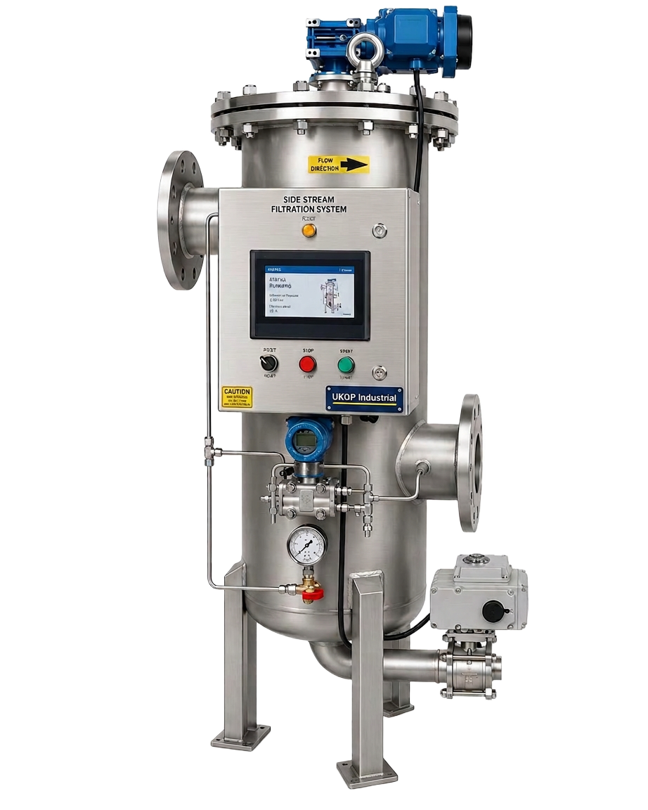
In any commercial heating installation, the low loss header manifold is only as effective as the water quality within the pipework. Compliance with BSRIA BG50 and BS 8552 is non-negotiable for site managers and FMs wanting to protect their assets. Particulate matter, such as magnetite and scale, can settle within the low flow area of the header, potentially causing blockages if not periodically flushed. Implementing a robust side-stream filtration strategy alongside the manifold is best practice for maintaining the integrity of the secondary loops. This ensures that even as the low loss header manifold balances the flows, the water itself remains free of abrasive suspended solids that could damage secondary pump seals or heat emitters.
Side-stream filtration works by processing a portion of the system volume through a high-efficiency filter, typically containing magnetic and fine-mesh elements. When used in conjunction with a low loss header manifold, it ensures that the decoupled circuits do not become a 'dead zone' for sludge accumulation. The UKGP range provides various options for filtration that can be easily integrated into the bypass of the main distribution headers. This preventative maintenance approach is significantly more cost-effective than acid cleaning or component replacement, particularly in large-scale residential blocks or commercial offices where downtime is extremely disruptive and costly.
Monitoring pH levels and chemical inhibitor concentrations is also vital. A chemical dosing pot should be installed to allow for the safe introduction of water treatment chemicals. By maintaining the correct chemistry, the internal surfaces of the low loss header manifold stay protected against corrosion. Engineers should regularly test the water at the header to ensure that it reflects the average condition of the system. This holistic approach to plant room design—combining hydraulic separation, mechanical filtration, and chemical treatment—is the hallmark of a high-performance HVAC system that meets modern CIBSE guidelines for efficiency and longevity.
- Integrate side-stream filtration to remove magnetite and scale.
- Install chemical dosing pots for easy maintenance of inhibitors.
- Adhere to BSRIA BG50 for closed-circuit water quality management.
- Monitor pH levels to prevent corrosion of the header internal surfaces.
Installation and Commissioning Best Practices
When installing a low loss header manifold, correct positioning is vital for both performance and future serviceability. It should be located as close to the boilers as possible to minimise the pressure drop in the primary circuit. The UKGP units come with pre-fitted insulation jackets, which is a critical feature for compliance with Part L of the Building Regulations, ensuring that standby losses are kept to an absolute minimum. Contractors should ensure that there is sufficient clearance for maintenance, especially at the drain-down point and the sensor pockets. Integrating a pocket-mounted temperature sensor within the header allows the BMS to monitor the actual flow temperature being delivered to the secondary manifolds.
Commissioning involves balancing the flow rates so that the secondary demand does not exceed the primary supply if temperature consistency is a priority. During the initial filling and venting of the low loss header manifold, installers must ensure that all air is purged to prevent 'air-binding', which can stop flow entirely. Using the threaded or flanged connections provided on UKGP headers, the unit can be securely mounted to the plant room floor or wall brackets. Because these units are rated up to 2000 kW, the weight of the water-filled vessel must be accounted for in the structural supports. The 2-year warranty provided by UKGP gives consultants peace of mind that the materials and welds are of the highest industrial standard.
Finally, insulation must be meticulously fitted around the header and all associated pipework. The included jackets are designed for easy removal, allowing for inspection during annual service visits. Proper insulation prevents the low loss header manifold from becoming a significant radiator in the plant room, which not only wastes energy but can lead to overheating of sensitive electronic controls and pumps. By following these installation steps and utilising UKGP's 2-3 week lead time for bespoke requirements, M&E contractors can ensure a professional, compliant, and efficient heat delivery system that stands up to the rigours of commercial operation.
- Locate the header close to the primary heat source.
- Use BMS-integrated sensors in the header pockets for precise monitoring.
- Ensure insulation jackets are correctly fitted to meet Part L requirements.
- Check support structures can handle the operating weight of the vessel.
Thermal Performance and Energy Efficiency
The energy efficiency of a commercial boiler plant is heavily dependent on the return water temperature. For condensing boilers to operate in their most efficient mode, the return water must be below the dew point, typically around 54°C. A correctly sized low loss header manifold facilitates this by preventing the mixing of high-temperature flow water directly into the return line, provided the flow rates are balanced correctly. If the primary pump is running much faster than the secondary pump, hot water will 'short-circuit' through the header and raise the return temperature, causing the boiler to drop out of condensing mode. This manifests as higher fuel bills and increased carbon emissions.
By utilising a low loss header manifold, engineers can create a 'buffer' that absorbs these variations in flow. This is particularly useful in multi-zone buildings like hotels or hospitals where the heat load can vary drastically within minutes. The header acts as a neutral point where the system can stabilise. UKGP's headers are designed with this thermal stability in mind, ensuring that the internal volume is sufficient to dampen flow fluctuations without being so large that it introduces significant thermal lag. This balance is key to achieving the high seasonal efficiencies demanded by CIBSE and modern carbon reduction targets.
For procurement leads, the decision to invest in a quality low loss header manifold is driven by the total cost of ownership. While cheaper, undersized units might save on initial capital expenditure, the subsequent increase in energy consumption and the risk of boiler damage far outweigh the savings. UKGP's 40-2000 kW range offers a robust middle ground, providing high-spec industrial manufacturing with the convenience of BSP or PN16 connections. These headers ensure that the heating system operates at its peak designed efficiency for the duration of its life cycle, backed by a 2-year warranty that reflects our confidence in the product's durability and performance.
- Optimise return temperatures to ensure continuous boiler condensation.
- Reduce carbon emissions by maintaining high seasonal efficiency.
- Prevent boiler short-cycling and premature component failure.
- Balance flow rates to avoid thermal short-circuiting within the header.
Material Specifications and Compliance Standards
The materials used in the construction of a low loss header manifold must be compatible with the system’s operating pressure and temperature. UKGP Industrial manufactures headers using high-grade carbon steel, finished with a protective coating to prevent external corrosion. For larger commercial applications, flanged PN16 connections provide a secure, leak-proof interface with the main pipework, while smaller systems can utilise BSP threaded options. All units are pressure tested to ensure they can withstand the rigours of commercial heating pressures, often exceeding 6 bar in many multi-storey applications. This adherence to manufacturing standards ensures the header remains a reliable part of the infrastructure for decades.
Compliance with BS EN 14917 and other relevant UK standards for pressure vessels is standard practice for UKGP. This ensures that every low loss header manifold we supply meets the safety requirements for occupied buildings. When selecting a header, it is important to verify that the manufacturer provides full technical documentation, including dimensions, mounting details, and flow capacities. This transparency allows consulting engineers to include the products in their BIM models and project specifications with total confidence. Our lead times of 2-3 weeks are designed to fit into the fast-paced schedules of UK construction projects, ensuring that critical path items like headers are on-site when needed.
In summary, the low loss header manifold is a fundamental component that dictates the hydraulic health of a commercial heating system. From ensuring the primary heat source is protected to providing a stable platform for secondary distribution, its role cannot be overstated. By choosing a UKGP low loss header (available from 40 to 2000 kW) with an included insulation jacket and a 2-year warranty, you are choosing a product designed for the demanding UK market. Contact our technical team today for a quote or to discuss your specific sizing requirements to ensure your next project benefits from perfect hydraulic separation and long-term operational reliability.
- High-grade carbon steel construction for industrial durability.
- PN16 flanged or BSP threaded connections for versatile installation.
- Pressure tested to meet stringent UK commercial safety standards.
- Includes a 2-year warranty for long-term peace of mind.
Frequently asked questions
What kW range do UKGP low loss headers cover?
- Our range of low loss headers covers systems from 40 kW up to 2000 kW, making them suitable for everything from light commercial units to large scale industrial plant rooms.
Are the low loss headers supplied with insulation?
- Yes, all UKGP low loss headers are supplied with a high-quality, tailored insulation jacket to comply with Part L regulations and minimise heat loss.
Can I get a header with flanged connections?
- Absolutely. We offer both BSP threaded connections for smaller systems and PN16 flanged connections for larger commercial pipework requirements.
What is the typical lead time for a low loss header manifold?
- The typical lead time for our standard commercial range of headers is 2-3 weeks from the point of order.
Does a low loss header manifold help with air and dirt removal?
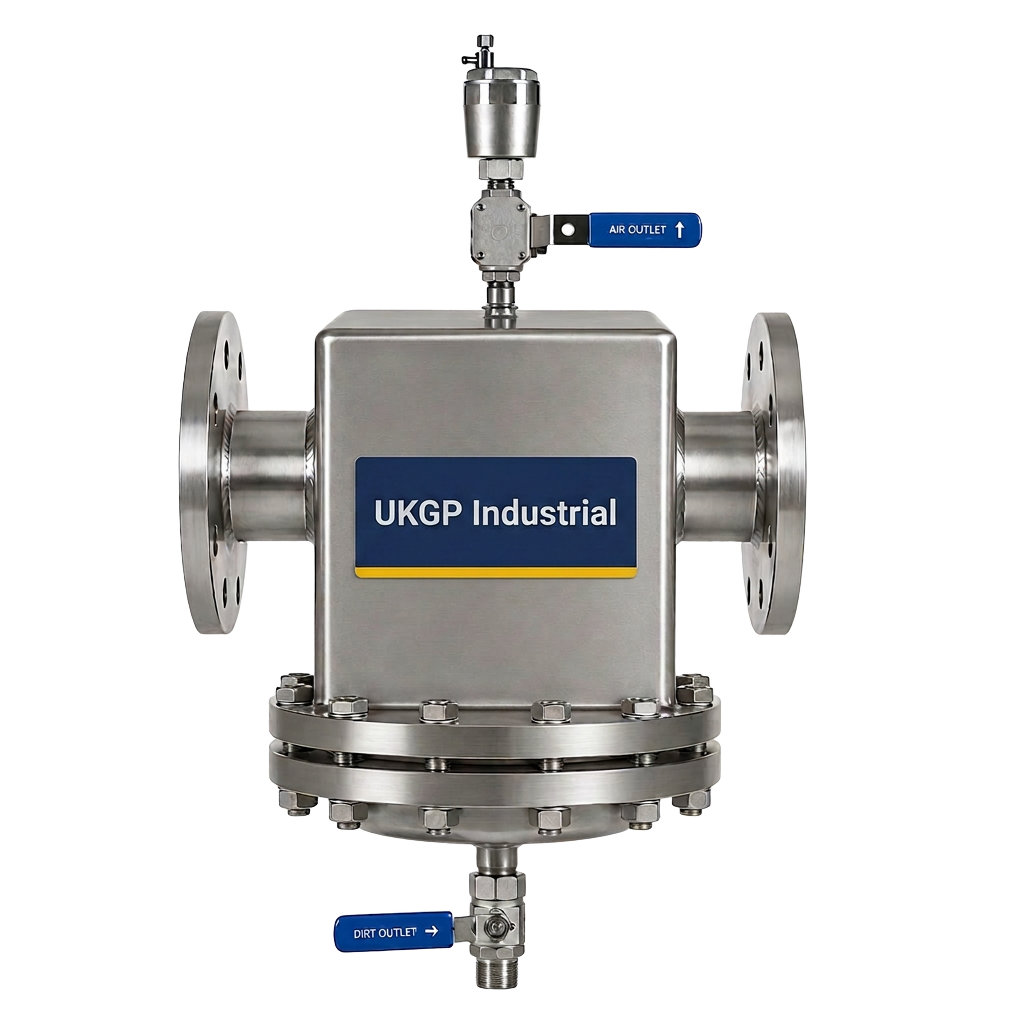
- Yes, the low-velocity zone within the manifold allows air to rise and dirt to settle, though for high-pollutant systems, we recommend dedicated air and dirt separators or side-stream filtration.