The Fundamentals of Hydraulic Separation in Commercial HVAC
Hydraulic separation is a cornerstone of modern plant room design, particularly when integrating modular condensing boilers with secondary circuits featuring high-head pumps. The primary objective of a low loss header is to create a zone of low pressure where the primary and secondary circuits can operate independently. This prevents the pumps from 'competing' with one another, which can otherwise lead to cavitation, shortened motor life, and inconsistent heat delivery. For building services consultants, ensuring that the primary flow speed is maintained regardless of secondary demand is essential for boiler protection and achieving the condensing efficiencies promised by manufacturers.
In this low loss header design guide, we emphasize that the header acts as a buffer, allowing for the balancing of flow rates where the secondary circuit demand may fluctuate significantly compared to the constant flow required by the heat source. Without this separation, variable speed drives on secondary pumps can interfere with the internal flow protocols of the boiler, often resulting in high-limit trips or thermal shock. Properly specifying the vessel ensures that the neutral point of the system is clearly defined, facilitating easier commissioning and more predictable performance during the seasonal variations typical of the UK climate, according to CIBSE guidelines.
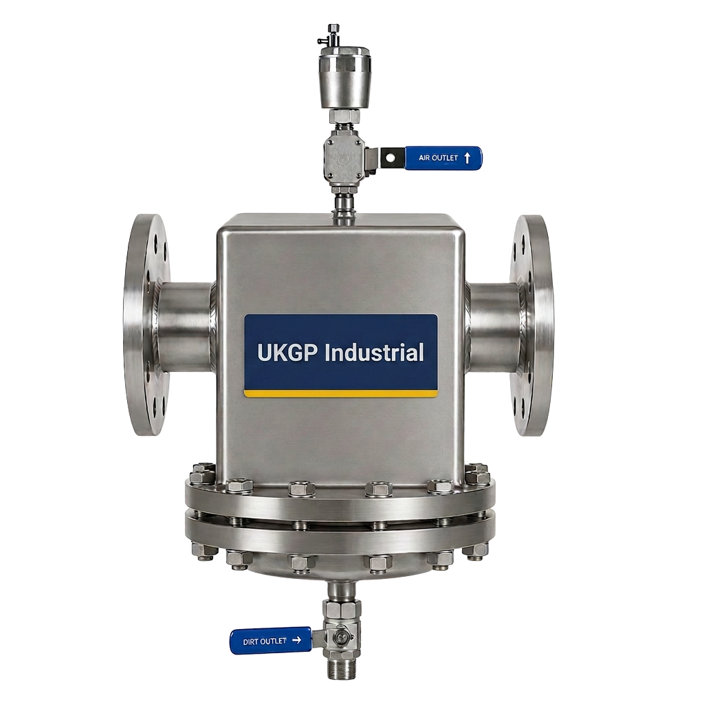
When consulting a low loss header design guide, it is vital to account for the impact of air and dirt on system longevity. While the header primarily manages hydraulics, it often serves as a secondary point for debris settlement and de-aeration due to the reduced velocity of the medium within the vessel. Integrating high-quality units with internal baffles or using them alongside dedicated air and dirt separators can significantly reduce the risk of blockage in heat exchangers and control valves. This dual-purpose approach supports the water quality standards outlined in BSRIA BG29 and BG50, which are critical for maintaining any manufacturer warranty on the primary equipment.
- Prevents pump conflict between primary and secondary circuits.
- Facilitates constant flow through boiler heat exchangers.
- Acts as a neutral pressure zone for system stability.
- Supports secondary circuits with high pressure drops.
Essential Low Loss Header Design Guide Sizing Principles
Sizing a low loss header is not merely about matching pipe diameters; it requires a calculated approach based on the maximum total flow rate of the system. A common rule of thumb found in any professional low loss header design guide is the 'four-to-three' ratio, though modern engineering software allows for more precise volumetric calculations. The internal velocity within the header should typically be kept below 0.5 metres per second to allow for effective hydraulic decoupling. If the velocity is too high, the 'neutral' zone is compromised, and kinetic energy from the primary circuit will begin to influence the secondary, defeating the purpose of the installation.
For UK engineers working on commercial projects ranging from 40 kW to 2000 kW, the selection process must also account for the temperature delta (ΔT). If you are designing for a condensing system with a 20-degree differential, the flow rates will be lower than a traditional 11-degree system, allowing for a more compact header. However, if the system is intended for heat pump integration or lower temperature radiators, the increased flow rates necessitated by a smaller ΔT will require a larger vessel diameter to maintain the target internal velocity. It is always better to slightly oversize a header than to undersize it, as the latter can create turbulent zones that disrupt temperature sensing.
UKGP Industrial provides a range of low loss headers designed exactly for these parameters, covering outputs from 40 kW up to 2000 kW. These units are available in both flanged (PN16) and threaded (BSP) configurations to suit any specification. When following a low loss header design guide, remember that the vertical orientation of the header is critical for promoting the separation of air (at the top) and sludge (at the bottom). Our units come with a 2-year warranty and a standard lead time of just 2-3 weeks, ensuring that project timelines are met without compromising on the technical integrity of the plant room layout.
- Maintain internal vessel velocity below 0.5 m/s.
- Size based on maximum possible flow rate of primary or secondary.
- Account for specific Delta T requirements of the heat source.
- Ensure vertical installation for optimal de-aeration and sludge collection.
Material Specification and Insulation Standards
The material composition of a low loss header is a critical factor for long-term durability in commercial environments. Most high-quality headers are manufactured from carbon steel, which provides the necessary structural integrity to handle the pressures found in large-scale M&E installations. According to this low loss header design guide, the internal finish and weld quality are paramount; poor welds can lead to micro-leaks or catch points for anaerobic bacteria and corrosion products. In the UK, compliance with the Pressure Equipment Directive (PED) and relevant British Standards ensures that the unit can withstand the operational stresses of a pressurized heating or cooling system.
Thermal efficiency is another non-negotiable aspect of modern design. Every low loss header should be supplied with a bespoke insulation jacket to prevent parasitic heat loss into the plant room. A high-grade mineral wool or EPP (Expanded Polypropylene) jacket significantly improves the overall efficiency of the thermal system. In many commercial settings, the plant room can become excessively hot, affecting the lifespan of electronic components and control panels. Proper insulation, as specified in your low loss header design guide, ensures that the heat remains within the fluid medium where it belongs, directly supporting the project's energy performance targets and BREEAM ratings.
Beyond the insulation, engineers must consider the connection types required for the specific project. Threaded BSP connections are generally suitable for smaller commercial applications up to approximately 100 kW, whereas larger systems typically require PN16 flanged connections for a more secure and robust seal. UKGP offers both options across our range, ensuring flexibility for contractors during the onsite installation phase. When you request a quote for our 40-2000 kW headers, we include the insulation jacket as standard, providing a complete solution that adheres to the best practices outlined in CIBSE technical memos and internal engineering specifications.
- Carbon steel construction for high-pressure reliability.
- Removable EPP or mineral wool insulation jackets for heat retention.
- Availability of BSP threaded and PN16 flanged connections.
- Corrosion-resistant external coatings for plant room longevity.
Integration with BSRIA Water Quality Protocols
Water quality management is perhaps the most overlooked aspect of low loss header integration. While the header manages flow, it also serves as a point where suspended solids can fall out of suspension due to reduced flow velocity. This makes it an ideal location for a drain valve to facilitate the removal of magnetic and non-magnetic debris. This low loss header design guide underscores the importance of adhering to BSRIA BG29 (Pre-commission cleaning) and BG50 (Water treatment for closed heating and cooling systems). If a header is not regularly purged of collected sludge, it can become a source of contamination rather than a protection device.
In addition to manual purging, the inclusion of a dosing pot in the system is essential for maintaining the correct chemical inhibitor levels. Our chemical dosing pots are often specified alongside low loss headers to ensure the easy introduction of biocides and corrosion inhibitors. This holistic approach ensures that the heat exchangers within the primary boilers remain free from scale and sludge, thereby maintaining the heat transfer efficiency over the lifetime of the system. Engineers should ensure that the low loss header is placed in a position that allows for easy access to the drain valve and the air vent to simplify these maintenance tasks.
The synergy between local water treatment and hydraulic separation cannot be overstated. By reducing the velocity of the water, the low loss header allows the air and dirt separators located elsewhere in the system to work more effectively by slowing down the passage of transit solids. When designing your plant room layout using this low loss header design guide, ensure that there is sufficient clearance for technicians to perform the BSRIA-mandated water testing. This proactive design ensures that the system operates within the specified pH and conductivity ranges, protecting the 2-year warranty offered on UKGP industrial equipment and the investments made in high-value boiler plant.
- Utilise header drain valves for removal of settled debris.
- Align system maintenance with BSRIA BG50 requirements.
- Ensure easy access for chemical dosing and water sampling.
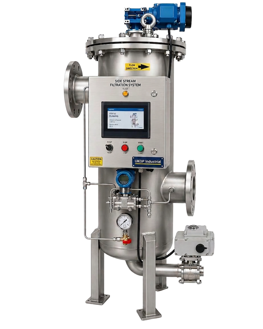
- Complement hydraulic design with robust side stream filtration.
Installation Best Practices and Sensor Placement
For a low loss header to function correctly, the placement of temperature sensors is vital. Most headers include dedicated sensor pockets, typically located in the top-third of the vessel to capture a representative temperature of the mixed flow. As noted in this low loss header design guide, if the sensor is placed too low, it may read the cooler return water, causing the boiler to fire unnecessarily and cycle frequently. Accurate sensor placement allows the Building Management System (BMS) to modulate the primary heat source precisely according to the actual demand of the secondary circuits, which is the key to achieving real-world energy savings in commercial systems.
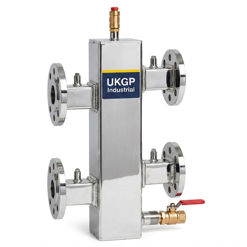
Piping geometry also plays a significant role in the performance of the decoupling zone. The distance between the primary flow and return connections on the header must be sufficient to prevent immediate mixing, which would dilute the flow temperature. It is standard practice to ensure the header is installed in a vertical orientation. This verticality facilitates the buoyancy of air bubbles towards the automatic air vent at the top and the gravity-assisted descent of sludge to the base. This vertical configuration is a non-negotiable standard in our low loss header design guide and is reflected in the design of UKGP units, which are engineered for optimal thermal layering.
Contractors should also be mindful of the support requirements for these vessels. A fully charged 2000 kW low loss header can be extremely heavy; therefore, robust floor stands or wall-mounting brackets must be specified. Our units are designed for ease of installation, with clear markings for flow and return to prevent cross-connection errors on site. By choosing a UKGP low loss header, you benefit from a design that has been refined through feedback from M&E contractors who demand both high performance and simple, reliable installation procedures. We offer technical support to ensure your specific configuration matches the hydraulic requirements of your project correctly.
- Locate temperature sensors in high-level pockets for accuracy.
- Always install in a vertical orientation for buoyancy-driven separation.
- Verify floor load capacity for large-capacity headers.
- Maintain minimum straight pipe runs where possible to reduce turbulence.
Commercial Benefits of Specification with UKGP Industrial
Selecting the right supplier for heating plant components is as much a commercial decision as a technical one. In the UK building services sector, lead times can often make or break a project schedule. UKGP Industrial addresses this by maintaining a standard 2-3 week lead time on our range of 40-2000 kW low loss headers. This allows contractors to maintain momentum on site without the delays often associated with bespoke European imports. Furthermore, our 2-year warranty provides peace of mind to Facilities Managers and building owners, ensuring that the critical heart of their heating system is protected by a UK-based manufacturer with technical expertise.
Cost-effectiveness is integrated into the design, not just the purchase price. By using this low loss header design guide to specify the correct size and connection type (whether flanged PN16 or threaded BSP), you reduce the need for expensive site modifications and pipe reducers. The included insulation jacket also means there are no hidden costs for lagging once the unit is installed. When you request a quote, you receive a transparent, technical proposal that meets the rigours of M&E procurement standards. Our headers are designed to last, using materials that resist the harsh conditions of constant commercial operation, from schools to hospitals and industrial plants.
In conclusion, a well-implemented low loss header is the most effective way to ensure the hydraulic integrity and efficiency of a commercial heating system. Applying the principles in this low loss header design guide will help avoid common pitfalls such as boiler short-cycling and pump starvation. Whether you are dealing with a small 40 kW retrofit or a large 2000 kW newly built energy centre, UKGP Industrial has the engineering solutions and the logistical capacity to support your project. Contact our Surrey-based technical team today for a quote and experience the benefit of UK-manufactured precision engineering in your next building services project.
- Short 2-3 week lead times for rapid project delivery.
- Standard 2-year warranty on all commercial models.
- Technical support from UK-based engineering experts.
- Comprehensive flanged or threaded options for all capacities.
Frequently asked questions
Why is a low loss header necessary in a system with variable speed pumps?
- It provides hydraulic decoupling, ensuring that the varying flow rates of the secondary pumps do not disrupt the constant flow required by the primary boiler circuit, preventing pump conflict and boiler errors.
What is the maximum capacity of UKGP low loss headers?
- Our standard range accommodates heating loads from 40 kW up to 2000 kW, with options for larger bespoke units upon request.
Do these headers come with insulation as standard?
- Yes, all our commercial low loss headers are supplied with a high-quality insulation jacket to minimize heat loss and improve system efficiency.
What are the common connection types for UK commercial projects?
- We offer both BSP threaded connections for smaller systems and PN16 flanged connections for larger industrial and commercial applications.
How does a low loss header help with air and dirt removal?
- The velocity of the water drops significantly inside the vessel, allowing heavy particles to settle at the bottom and air bubbles to rise to the top, where they can be removed via a drain valve and air vent.