Understanding the low loss header calculator requirements
When performing sizing calculations for commercial heating systems, the primary objective is to ensure that the primary circuit flow—the volume of water moved by the boiler pumps—is slightly greater than the secondary circuit demand. A low loss header calculator facilitates this by converting the total heat load in kilowatts (kW) into a required flow rate using the specific heat capacity of water. For high-output UK plant rooms ranging from 40 kW to 2000 kW, precision is non-negotiable to prevent short-cycling of modern condensing boilers. Consultants frequently use these tools to establish the correct diameter of the vessel, typically keeping the vertical velocity within the header below 0.5 metres per second to allow for efficient air and dirt separation in accordance with CIBSE guidelines.
The mathematical formula underpinning a standard low loss header calculator is derived from Q = m x c x ΔT, where Q represents the heat load and ΔT is the temperature difference between the flow and return. In many modern UK commercial installations, a ΔT of 20°C is standard for condensing boilers to maximise efficiency, whereas older systems may still operate on an 11°C differential. Changing these variables significantly alters the required flow rate, which in turn dictates whether you require a BSP threaded header for smaller applications or a PN16 flanged vessel for larger industrial loads. Our technical team regularly supports contractors in validating these calculations to ensure that the physical hardware matches the peak thermal demand of the building.
Failure to use a verified low loss header calculator can lead to hydraulic imbalances that compromise the longevity of the entire HVAC infrastructure. If the header is undersized, the pressure drop across the vessel becomes significant, effectively nullifying the 'low loss' benefit and causing the primary and secondary pumps to compete. This competition leads to erratic temperature control and increased mechanical wear. By ensuring the calculation accounts for the maximum possible flow rate of both circuits, engineers provide a ‘neutral zone’ where pressure is negligible, allowing each pump to operate at its design duty without interference from downstream valves or secondary circuit fluctuations.
- Heat load input in kW for accurate volumetric flow sizing
- Temperature differential variables (ΔT) for condensing vs non-condensing
- Velocity limits to ensure hydraulic decoupling and air release
- Pressure drop considerations for BSRIA BG29 compliance
Sizing for Efficiency: kW to Flow Rate Conversion
Translating a total building heat load into a workable flow rate is the core function of any professional low loss header calculator. For instance, a 500 kW system operating at a 20°C Delta T requires a flow rate of approximately 21.5 cubic metres per hour. Once this flow rate is established, the physical dimensions of the header must be selected to ensure that the internal velocity remains low enough to allow for effective hydraulic separation. UKGP provides a wide range of flanged PN16 units that cater to these specific high-flow requirements, ensuring that even at peak demand, the plant room remains stable and the boilers operate within their high-efficiency condensing parameters.
Beyond simple flow calculations, engineers must consider the physical orientation of the low loss header. While vertical headers are most common due to their ability to facilitate air and dirt removal, horizontal configurations are occasionally used where plant room height is restricted. A comprehensive low loss header calculator should ideally provide the volume of the vessel, which contributes to the overall system water content and thermal inertia. Increased inertia can be beneficial for reducing boiler cycling frequency. All UKGP headers come with an insulation jacket as standard to minimise standing heat losses, which is a critical factor for BREEAM assessments and general energy efficiency targets in modern UK commercial developments.
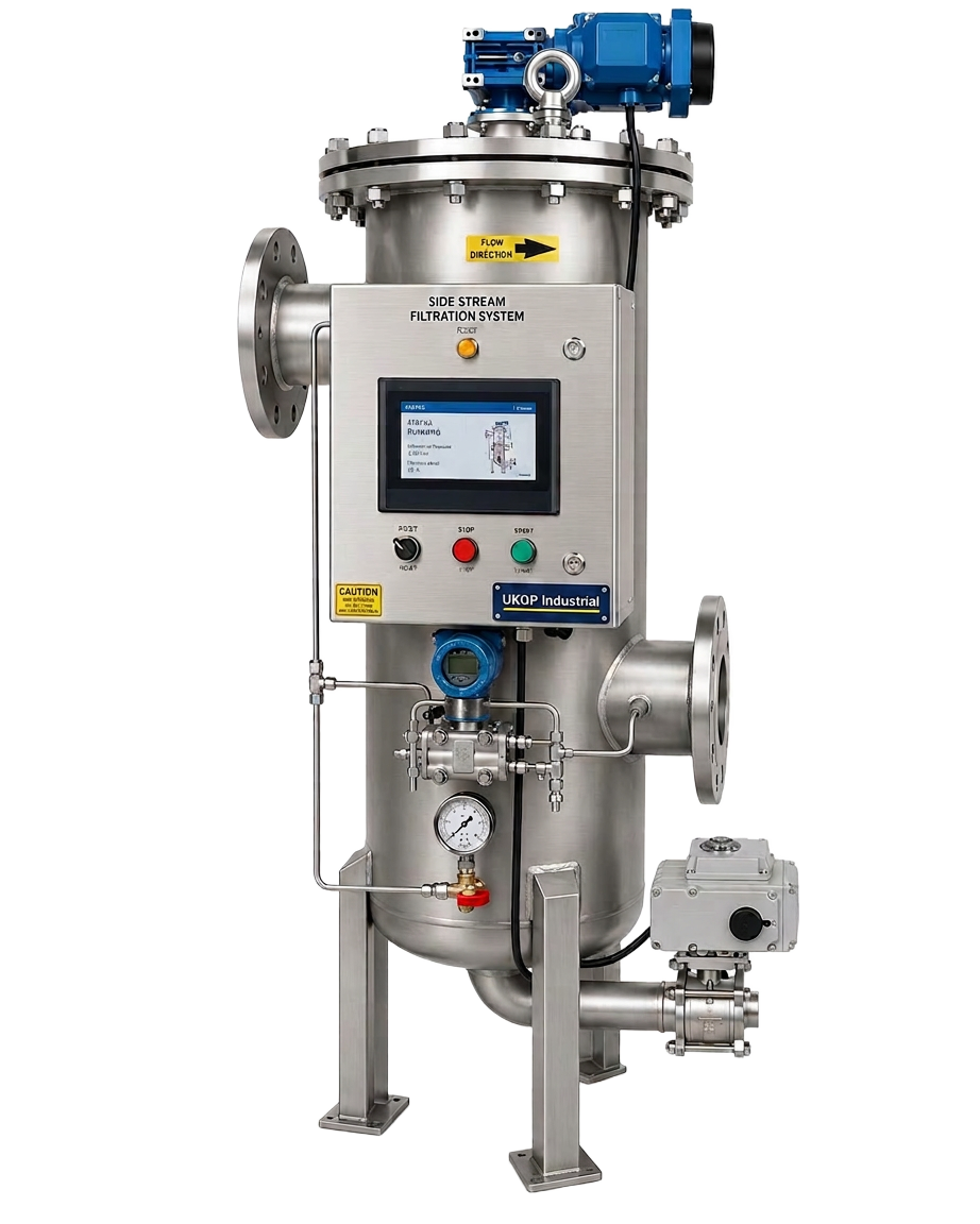
Maintenance and water quality, governed by BSRIA BG50, are also impacted by the sizing of the header. If the flow rate is calculated correctly, the header acts as a collection point for heavy particulate matter. Incorporating a drain valve at the base of a properly sized header allows for the removal of sludge before it reaches the heat exchangers. For comprehensive system protection, we often recommend pairing a correctly sized header with our side-stream filtration units to maintain optimal water chemistry. Integrating these components ensures that the calculated flow rates aren't restricted over time by the build-up of magnetite or other debris within the secondary pipework.
- Accurate kW to m³/h conversion for pump selection
- Integration of insulation jackets to meet Part L requirements
- Provision for drain points to facilitate BG50 maintenance
- Compatibility with variable speed drive (VSD) pumps
Technical Specifications and British Standards
When specifying hardware based on results from a low loss header calculator, compliance with British Standards is paramount. Pressure vessels used in commercial heating must be manufactured to withstand the maximum operating pressures of the system, typically PN16 for larger UK plant rooms. UKGP headers are designed with these rigours in mind, offering flanged or BSP threaded connections that suit everything from small 40 kW commercial units to massive 2000 kW industrial arrays. The use of high-grade carbon steel ensures durability, while our 2-year warranty provides peace of mind for M&E contractors and facility managers responsible for long-term site performance.
The physical construction of the header should also include tapping points for temperature sensors and air vents. Accurate temperature data is vital for the Building Management System (BMS) to modulate the primary heat source based on actual secondary demand. If the low loss header calculator suggests a large diameter vessel, ensures that the sensor pockets are deep enough to provide a representative reading of the blended water temperature. This level of technical detail is what separates a standard pipework ‘bridge’ from a true hydraulic separator. Our lead times are typically 2-3 weeks, allowing projects to remain on schedule even when bespoke sizing is required for complex retrofits.
Finally, consideration must be given to the thermal expansion of the system fluid. While a low loss header provides hydraulic separation, it does not replace the requirement for correctly sized expansion vessels or bellows. According to BS EN 14917, compensating for thermal growth in large-diameter pipework is essential to prevent mechanical stress on the header's connections. By coordinating the low loss header calculator outputs with the wider system design, engineers can ensure that all components—from the primary boilers to the terminal units—function as a cohesive, reliable system that meets the stringent demands of modern UK building services regulations.
- Adherence to PN16 pressure ratings for commercial safety
- Threaded BSP or flanged connection options for versatility
- Lead times of 2-3 weeks for fast-track UK projects
- Integration with BMS via strategically placed sensor pockets
Optimising Primary and Secondary Flow Balance
The role of the low loss header is to act as a point of zero pressure drop, where the primary and secondary circuits meet but remain decoupled. Achieving this state requires that the flow rate calculated by the low loss header calculator is respected throughout the installation phase. If the secondary circuit attempts to pull more water than the primary circuit provides, the header will experience a 'mixing' effect where return water is drawn back into the flow, lowering the temperature delivered to the building. This is common in systems where the pump heads have not been correctly balanced or where the header is significantly undersized for the peak kW load.
Conversely, when the primary flow exceeds the secondary demand, the excess heated water bypasses the secondary circuit and returns directly to the boiler. For condensing boilers, this can be problematic if the return temperature rises above the dew point (approximately 54°C), as it prevents the boiler from recovering latent heat. A precise low loss header calculator helps engineers find the 'sweet spot' where temperature stratification is maintained and the boiler return temperature remains as low as possible. This balance is critical for achieving the high seasonal efficiencies promised by modern boiler manufacturers and required by CIBSE Heat Networks Code of Practice.
For plant room engineers, the practical application of these calculations often happens during the procurement phase. When you request a quote for a UKGP low loss header, we look at your kW and flow requirements to ensure the vessel supplied will handle the peak loads without creating turbulence. Our standard range covers 40-2000 kW, providing a robust solution for diverse applications from schools to high-rise residential blocks. Each unit is finished to a high standard and ready for immediate integration into your primary pipework, complete with a 2-year warranty to support your professional indemnity and site handover requirements.
- Prevention of return-water mixing to preserve flow temperatures
- Protection of the condensing cycle for maximum fuel economy
- Standardised sizing for 40 kW to 2000 kW plant capacities
- Robust carbon steel construction for industrial longevity
Installation Best Practices for Hydraulic Separators
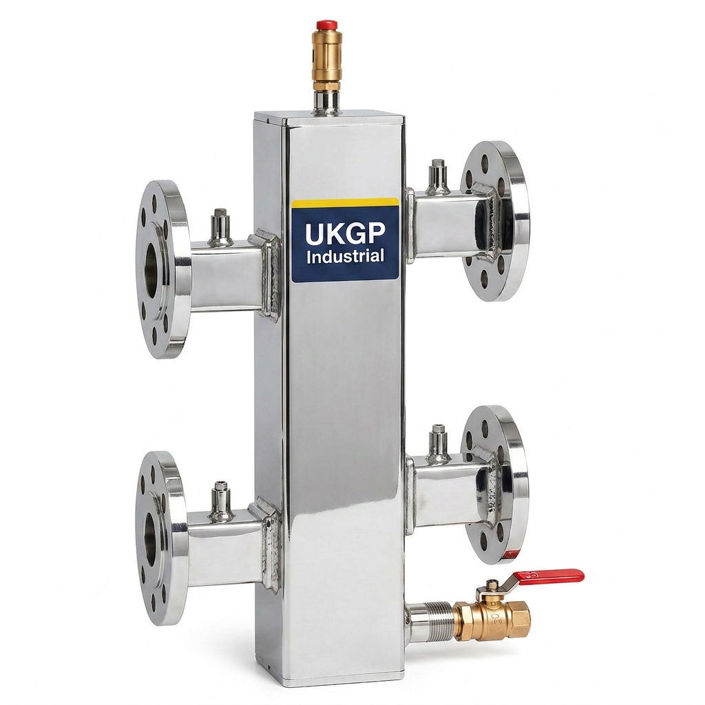
Once the low loss header calculator has provided the necessary dimensions, the installation layout must follow BSRIA recommendations to ensure the theoretical performance is met in practice. The header should be installed vertically to promote the buoyancy of air bubbles towards the automatic air vent (AAV) at the top. This also allows the bottom of the vessel to act as a low-velocity zone where dirt and magnetite can settle via gravity. UKGP headers are designed with the appropriate tapping heights to ensure that the primary and secondary connections do not induce internal turbulence, which would otherwise disrupt the hydraulic 'null' point.
Pipework connections to the header should be sized to match the header's inlet and outlet ports to avoid sudden velocity changes. Using a low loss header calculator to determine the pipe sizes often results in choosing flanged PN16 connections for flows exceeding 5 litres per second. It is also essential to ensure that the header is properly supported; while the pipework provides some stability, the weight of a water-filled 2000 kW header is substantial. Using a dedicated support cradle or floor-standing bracket prevents stress on the boiler's connections and ensures the long-term integrity of the plant room's hydraulic architecture.
Commissioning agents should verify the flow rates through the header using ultrasonic flow meters or fixed balancing valves. If the measured flow deviates significantly from the results of the low loss header calculator, it may indicate a bypass elsewhere in the system or an incorrectly set pump speed. Rectifying these issues during the commissioning phase (BG29) is far more cost-effective than troubleshooting a failing system during the peak of winter. By choosing a UKGP header, you are installing a component engineered to these specific tolerances, backed by technical support that understands the nuances of UK building services.
- Vertical installation to facilitate air and dirt separation
- Matching pipework diameters to vessel ports to maintain velocity
- Adherence to BSRIA BG29 commissioning protocols
- Ensuring structural support for high-volume 2000 kW vessels
Commercial Benefits of Correct Header Specification
From a procurement perspective, the decision to use a high-quality low loss header based on a rigorous low loss header calculator provides significant commercial protection. It reduces the risk of expensive remedial works following the discovery of hydraulic conflicts or 'noisy' pipework. For facility managers, a correctly sized and insulated header reduces energy consumption by ensuring that the pumps are not working against each other and the boilers are operating at their design efficiency. The inclusion of an insulation jacket with every UKGP header is not just a thermal requirement; it is a commercial necessity to meet modern energy performance certificates (EPCs).
Working with a UK-based manufacturer like UKGP Industrial offers advantages in logistics and lead times. While many European competitors require 6-8 weeks for delivery, we can typically supply a 40-2000 kW low loss header in 2-3 weeks. This speed is vital for reactive maintenance or fast-paced construction schedules where the plant room is the critical path. Furthermore, having a 2-year warranty on a PN16 flanged or BSP threaded unit ensures that any manufacturing defects are covered, protecting the contractor's margin and the client's long-term investment in their infrastructure.
In summary, the use of a low loss header calculator is the first step in a successful HVAC installation. It bridges the gap between the theoretical heat load and the physical reality of the plant room. By selecting UKGP as your supplier, you gain access to high-performance hydraulic separators that are bespoke-sized for your project's specific flow rates. Whether you are designing for a small 40 kW commercial project or a massive 2000 kW district heating scheme, our headers provide the hydraulic decoupling, air separation, and dirt collection required to meet BSRIA and CIBSE standards.
- Reduced risk of hydraulic short-circuits and pump failure
- Rapid 2-3 week lead time for UK commercial sites
- 2-year warranty on all header units (40-2000 kW)
- Improved energy ratings through standard thermal insulation
Frequently asked questions
What information do I need for a low loss header calculator?
- You primarily need the total system heat load in kilowatts (kW) and the design temperature differential (Delta T) between the flow and return. Standard values are 11°C for older systems or 20°C for modern condensing boiler plants.
How does flow rate affect the size of the header?
- Higher flow rates require a larger header diameter to keep the internal water velocity below 0.5 m/s. This low velocity is crucial for effective hydraulic separation and the removal of air and dirt particulates.
Are UKGP headers insulated as standard?
- Yes, all our low loss headers, ranging from 40 kW to 2000 kW, come with an insulation jacket as standard to assist with energy compliance and reduce plant room heat gains.
Can I get a flanged low loss header for a high-pressure system?
- Absolutely. We supply both BSP threaded options for smaller systems and PN16 flanged headers for larger commercial and industrial applications, typically within a 2-3 week lead time.
What is the standard warranty on UKGP low loss headers?
- Our headers come with a 2-year warranty, reflecting our confidence in the high-grade carbon steel construction and technical design of our 40-2000 kW range.