The Mechanics Inside a Low Loss Header
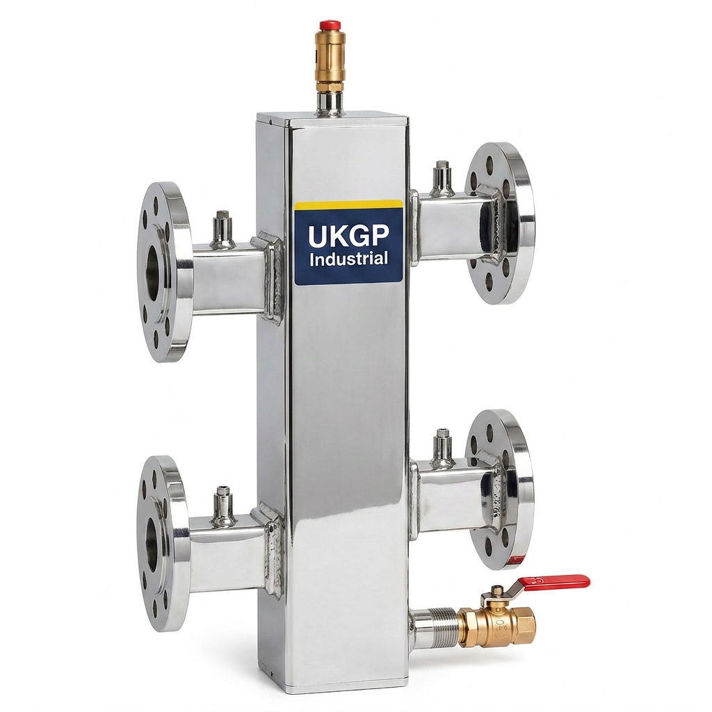
To understand the technical profile inside a low loss header, one must envision a chamber of low-velocity fluid that acts as a neutral point for the entire hydronic system. In a standard UKGP 40-2000 kW unit, the primary circuit from the heat source enters the vessel while the secondary distribution circuit pulls from the opposite side. The internal cross-sectional area is significantly larger than the connecting pipework, which causes a drastic reduction in water velocity. This velocity reduction is the fundamental principle that allows the primary and secondary pumps to operate independently without creating a series-circuit conflict that could lead to premature motor failure or erratic temperature control.
From a thermal perspective, the action inside a low loss header manages the temperature delta between flow and return precisely according to system demand. When the secondary load matches the primary generation, the water passes straight through with minimal mixing. However, in modern condensing boiler applications, maintaining a low return temperature is critical to remain in the condensing mode for maximum efficiency. The vessel allows for bypass flow if the secondary demand is lower than the primary flow, protecting the heat exchanger from low-flow conditions while ensuring the rest of the building services remain stable and responsive to BMS commands.
Engineering consultants often specify these vessels to combat the complexities of variable flow systems. By looking at a cutaway inside a low loss header, you would see how the vessel dampens the pressure variations caused by two or more sets of pumps working in tandem. This ensures that the primary circuit pumps, which are often integrated into the boilers, are not physically dragged or pushed by more powerful secondary circulators. This separation is a key recommendation in CIBSE guidance and BSRIA BG50 design protocols, particularly when retrofitting high-efficiency plant into older commercial buildings with existing distribution pipework.
- Reduces water velocity to facilitate hydraulic decoupling
- Prevents pump conflict in multi-circuit systems
- Supports condensing boiler efficiency by managing return temperatures
- Acts as a buffer to absorb pressure fluctuations
Hydraulic Separation and BSRIA Standards
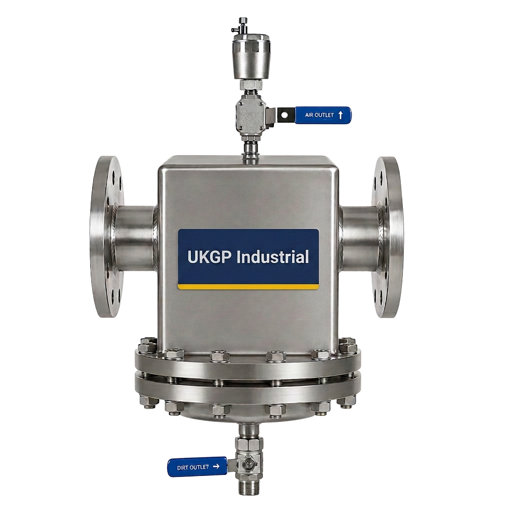
In accordance with BS 8552 and BSRIA BG29/2020, the management of water quality and flow stability is paramount for the long-term integrity of commercial HVAC assets. When we examine the flow profile inside a low loss header, we see that it acts as more than just a hydraulic bridge; it serves as a critical junction for debris management. Many modern low loss headers incorporate internal baffles or magnetic inserts to assist in the capture of magnetite and other suspended solids. By slowing the water down, the vessel allows heavier particles to settle at the base, which can then be safely flushed through a dedicated drain valve during routine maintenance visits.
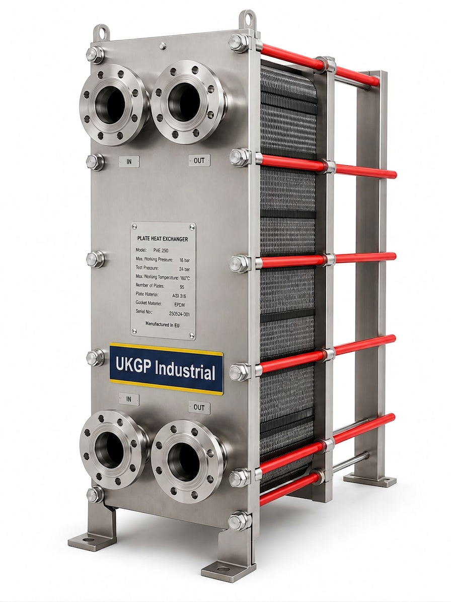
The interaction inside a low loss header also plays a vital role in air management. As the fluid velocity drops, entrained air bubbles are more likely to rise to the top of the vessel, where they can be purged via an automatic air vent. This dual-purpose design aligns with BSRIA BG50 requirements for air and dirt separation in closed-loop systems. By removing these contaminants at the source, M&E contractors can significantly reduce the risk of localized corrosion or blockage in sensitive downstream components like plate heat exchangers or control valves. This proactive approach to system cleanliness is essential for achieving the design life of the plant-room assets.
When specifying a low loss header for a commercial project, it is vital to account for the total system volume and the maximum flow rate calculated for the primary chargers. A poorly sized vessel will fail to provide the necessary hydraulic decoupling, leading to turbulent mixing that can disrupt the system's temperature stratification. For bespoke Surrey-based projects or national rollouts, UKGP Industrial provides flanged or threaded options (BSP/PN16) that are pre-insulated with high-quality jackets to minimize heat loss. These units are designed to handle capacities from 40 kW up to 2000 kW, ensuring coverage for everything from small schools to large district heating schemes.
- Complies with BSRIA BG29/50 water quality guidelines
- Facilitates passive air and dirt separation
- Reduces turbulent mixing to maintain temperature stratification
- Includes high-quality insulation to meet building regulation compliance
Internal Flow Patterns and Thermal Stratification
The thermal stratification inside a low loss header is what allows for precise control of the heat distribution. In a heating application, the hottest water settles at the top of the vessel, while cooler return water sits at the bottom. This gravity-assisted separation ensures that the secondary flow receives the highest possible temperature while the primary return stays as cool as possible to facilitate boiler condensing. Engineers must ensure that sensors are placed correctly in the header’s pockets to provide accurate data to the BMS, allowing for real-time adjustments to burner firing rates and pump speeds based on the actual vessel temperature.
Within the internal chamber, three distinct flow conditions can occur depending on the balance of the system. If primary flow exceeds secondary demand, the excess hot water bypasses the secondary circuit and returns to the boiler, raising the return temperature. Conversely, if secondary demand exceeds primary supply, cool return water is sucked into the secondary flow, diluting the delivery temperature. This 'mixing' behavior inside a low loss header must be carefully managed to avoid cold-bridge issues or insufficient heat delivery to terminal units. Proper sizing based on the peak flow rates of both circuits is the only way to ensure the vessel operates within its designed performance parameters.
From a construction perspective, the internal surfaces of the header are often untreated or epoxy-coated depending on the application. UKGP Industrial units feature robust steel construction and are pressure tested to ensure integrity under the high-stress conditions of a commercial plant-room. With a 2-year warranty and lead times of just 2-3 weeks, these headers are becoming the standard choice for UK contractors who cannot afford project delays. Whether you require a PN16 flanged unit for a high-rise project or a BSP threaded vessel for a smaller plant-room, understanding the dynamics inside a low loss header helps in selecting the correct configuration for the job.
- Supports three distinct flow scenarios for maximum flexibility
- Enables precise sensor placement for BMS integration
- Durable steel construction with rigorous pressure testing
- Short 2-3 week lead times for time-critical UK projects
Integration with Secondary Filtration Systems
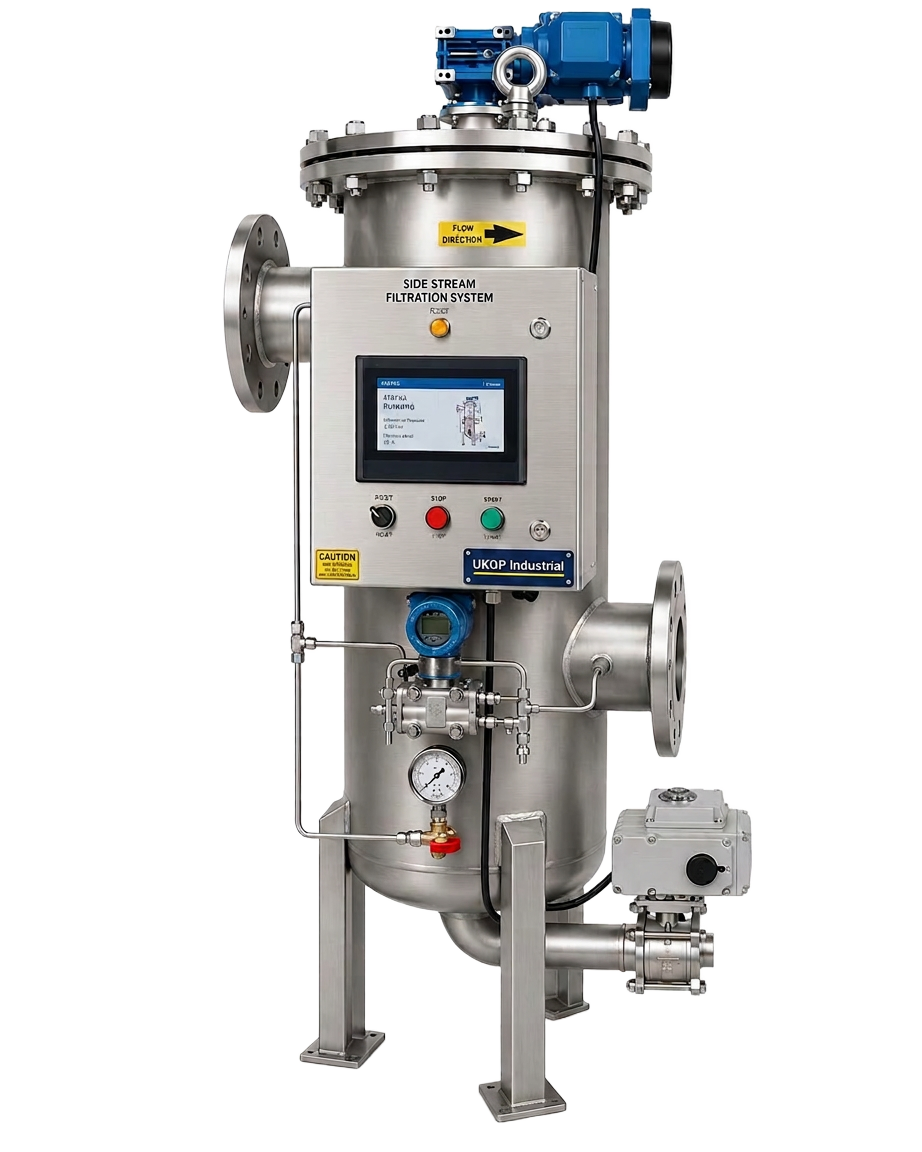
While the flow inside a low loss header helps settle some debris, it should not be the only line of defence in a BSRIA-compliant system. Integrating the header with side stream filtration ensures that even the smallest micron-level particles are removed from the loop. The neutral pressure zone created within the low loss header provides an ideal take-off point for side stream loops, as it allows for consistent flow through the filter media regardless of the fluctuations in the main distribution pipes. This synergy between hydraulic separation and high-efficiency filtration is a hallmark of modern sustainable building design.
Contractors often find that installing a UKGP expansion bellows nearby can further protect the low loss header from the stresses of thermal expansion. Because the header is a fixed point where multiple pipes converge, the expansion and contraction of long pipe runs can exert significant mechanical force on the header's nozzles. By installing bellows, these movements are absorbed, preventing leaks at the threaded or flanged connections. This holistic view of the plant-room layout—considering everything from the internal flow inside a low loss header to the external mechanical stresses—leads to a more resilient and reliable HVAC installation for the end client.
Maintenance is simplified when the system is designed with a clear understanding of the internal vessel dynamics. Because the low loss header serves as the 'hub' of the plant-room, it is often the first place engineers look when troubleshooting temperature or pressure issues. If the temperature differential across the header is not as predicted, it often points to an imbalance in the pump commissioning or a blockage in the primary heat exchangers. By specifying a UKGP unit with integrated sensor pockets and drain points, FM teams can quickly diagnose and rectify issues, ensuring the building remains comfortable and energy-efficient throughout the heating season.
- Pairs with side stream filtration for total system protection
- Protected from mechanical stress through high-grade expansion bellows
- Simplifies plant-room troubleshooting and commissioning
- Centralised hub for temperature and pressure monitoring
Comparing Flanged and Threaded Connections
The physical entry points that lead to the chamber inside a low loss header are typically offered in two main configurations: BSP threaded or PN16 flanged. For smaller commercial loads up to 150 kW, threaded connections are often preferred for their ease of installation and reduced space requirements. However, for larger industrial applications up to 2000 kW, flanged connections are standard due to their superior structural integrity and ease of maintenance. UKGP Industrial provides both options, ensuring that the plant-room layout can be optimized for the specific constraints of the site, whether it is a tight basement retrofit or a new-build energy center.
When choosing the connection type, one must also consider the insulation requirements. All UKGP low loss headers come with a high-performance insulation jacket as standard. This is critical for complying with Part L of the Building Regulations, which demands minimal heat loss from plant-room pipework and vessels. The jacket is designed to fit snugly around the vessel, including the connection points, ensuring that the thermal energy managed inside a low loss header is delivered where it is needed rather than being wasted in the plant-room. This attention to detail reduces the operational carbon footprint of the building and lowers energy bills for the facility manager.
Lead times are a critical factor for M&E contractors working on tight schedules. UKGP’s ability to deliver these specialized vessels within 2-3 weeks, complete with a 2-year warranty, provides peace of mind in a market often plagued by supply chain disruptions. By choosing a manufacturer that understands the technical nuances—from the internal baffle design to the external finish—procurement leads can confidently source components that meet the rigorous standards expected in the UK B2B sector. Requesting a quote for a 40-2000 kW low loss header today ensures your project remains on track and performs to its maximum design potential.
- Available in BSP threaded or PN16 flanged variants
- Supplied with standard-compliant insulation jackets for Part L
- Covers a massive range from 40 kW to 2.0 MW
- Fast 21-day turnaround for standard UK specifications
Securing Your Plant Room Performance
In conclusion, the engineering that resides inside a low loss header is the silent guarantor of hydraulic stability. Without this component, modern variable speed pumping systems would struggle with bypass issues and pressure spikes, leading to increased maintenance costs and potential component failure. By providing a neutral zone where the primary and secondary circuits can interact safely, the header protects the most expensive parts of the system—the boilers and chillers—from the erratic demands of the building’s occupants. It is a simple yet vital piece of the energy-efficiency puzzle in any commercial development.
Specifying the right equipment means looking beyond the price tag to the technical support and reliability of the supplier. UKGP Industrial’s low loss headers are engineered to meet the demands of the UK’s harshest heating environments. With a 2-year warranty backing every unit and a range that extends to 2000 kW, these headers are designed to last. The practical benefits—such as the ease of flushing debris and the straightforward integration with BMS sensors—make them a favorite among plant-room engineers and facility managers who prioritize long-term performance over short-term savings.
Whether you are designing a system for a new hospital, a university campus, or a retail hub, understanding the flow inside a low loss header will help you create a more robust HVAC design. Don't leave your hydraulic separation to chance; choose a vessel that has been manufactured to the highest standards with the needs of the UK installer in mind. Reach out to the UKGP technical team today to discuss your specific requirements, from flanged PN16 configurations to fast-track delivery schedules. Our units are ready to provide the separation and protection your high-efficiency plant-room deserves.
- Protects expensive heat sources from hydraulic instability
- Designed for longevity in high-demand commercial environments
- Supported by technical expertise and 2-year warranty cover
- The essential choice for energy-efficient building services
Frequently asked questions
What is the primary function inside a low loss header?
- The primary function is to provide hydraulic separation, allowing the primary (heat source) and secondary (distribution) circuits to operate at different flow rates and pressures without interfering with each other.
How does water velocity change inside a low loss header?
- Water velocity drops significantly due to the increased cross-sectional area of the vessel. This low-velocity zone allows for the decoupling of pump circuits and facilitates the settling of debris and the release of entrained air.
What size low loss header do I need for a 1000 kW system?
- Sizing is based on the maximum flow rate of either the primary or secondary circuit (whichever is greater). UKGP offers units for 1000 kW and above, available in flanged PN16 configurations to suit industrial demands.
Does a low loss header require an insulation jacket?
- Yes, to comply with UK Building Regulations Part L and to prevent heat loss in the plant-room, all low loss headers should be fitted with an insulation jacket, which is provided as standard with UKGP units.
What is the lead time for a UKGP low loss header?
- Our standard lead time for commercial low loss headers (40-2000 kW) is approximately 2 to 3 weeks, making them ideal for both planned installations and urgent replacements.