The Fundamentals of a Hydraulic Separator explained
In modern commercial heating and cooling systems, the hydraulic separator serves as the critical junction point that decouples the primary production circuit from the secondary distribution circuits. While often used interchangeably with other terms, this component is specifically engineered to allow independent flow rates in both circuits without interference. For a plant room engineer, implementing a hydraulic separator ensures that the primary pumps serving the boilers or heat pumps are not fighting against the variable speeds of the secondary pumps serving the fan coil units or radiators. This decoupling is fundamental to preventing the 'hunting' of variable speed drives and ensuring that the heat source operates within its designed temperature differential (Delta T).
The physics within the vessel relies on a low-velocity zone where the pressure drop is almost negligible. By providing a common pipe area with a significantly larger cross-section than the connecting pipework, the water velocity drops to a point where the primary and secondary flows can mix or bypass each other based on demand. In the context of BSRIA BG29 pre-commission cleaning and BG50 water treatment for closed heating systems, these vessels often act as a focal point for debris management. If the vessel is sized correctly according to CIBSE guidelines, it prevents high-velocity turbulence that could otherwise lead to erosion or the bypass of air bubbles into the heat exchanger surfaces.
Choosing between different types of decoupling equipment often comes down to the volumetric capacity and the integration of secondary functions like air and dirt removal. UKGP Industrial specializes in bridging the gap between standard off-the-shelf units and high-performance engineered solutions. We provide vessels that address these hydraulic challenges head-on, ensuring that your system design remains robust under variable load conditions. When you are assessing your plant room layout, it is vital to remember that the separator is the 'heart' that manages blood flow—diverting it where needed without stressing the pump motors beyond their electrical and mechanical limits.
- Eliminates pump conflict between primary and secondary circuits.
- Facilitates constant flow through the heat source regardless of demand.
- Reduces high-velocity noise and mechanical wear on valves.
- Provides a neutral pressure zone for accurate sensor readings.
Low Loss Headers vs Hydraulic Separators
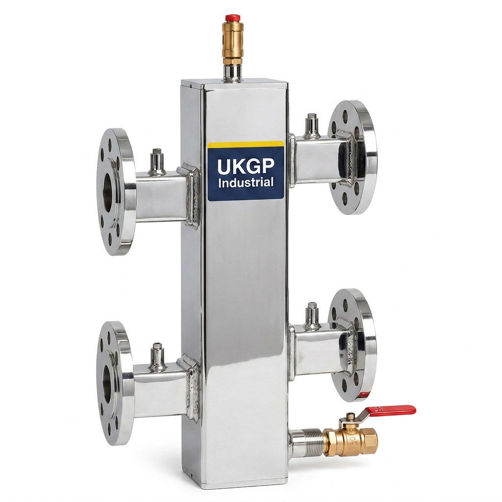
While the term 'low loss header' is the stalactite of UK plant room terminology, a hydraulic separator is technically the broader category to which it belongs. The primary goal of a low loss header is to achieve a low pressure drop (or loss) between the flow and return headers. This allows the primary circulator and the secondary distribution pumps to operate autonomously. For UK building services consultants, the decision often rests on space constraints and the specific kilowatts (kW) of the heat source. A well-designed low loss header provides an elegant solution for systems ranging from 40 kW up to 2000 kW, providing the necessary buffer to prevent short-cycling of high-efficiency condensing boilers.
From a commercial perspective, the UKGP low loss header range is designed to cater to 40-2000 kW applications with both flanged (PN16) and threaded (BSP) connections. These units are more than just hollow cylinders; they are precision-engineered vessels that ensure the return water temperature is managed effectively to maximize boiler condensing. In accordance with BS EN 12828, the inclusion of such a vessel is often the difference between a system that meets its seasonal efficiency targets and one that suffers from premature component failure. Our units come equipped with a high-quality insulation jacket to minimize standby heat losses, which is a critical factor for BREEAM and Part L compliance.
When specifying these units for a project with a 2-3 week lead time requirement, engineers must look at the physical orientation. A vertical low loss header is often preferred as it naturally aids in the separation of air (at the top) and debris (at the bottom). This aligns with BSRIA BG50 recommendations regarding the continuous removal of suspended solids. UKGP Industrial offers these units with a 2-year warranty, giving M&E contractors peace of mind that the hydraulic heart of the project is built to last. Whether you need a small 2-inch BSP unit or a massive DN300 flanged header, the principle of hydraulic decoupling remains the same: protect the plant and stabilize the flow.
- Available in 40-2000 kW capacities for all commercial scales.
- Options for BSP threaded or PN16 flanged connections.
- Includes a thermal insulation jacket to improve system EPC ratings.
- Standard 2-3 week lead time for fast-track UK projects.
Hydraulic Separator Sizing and CIBSE Standards
Correct sizing of a hydraulic separator is not merely a matter of matching connection sizes to the pipework. It is a calculation based on the maximum flow rate required by either the primary or secondary circuit. If the vessel is undersized, the velocity remains too high, and the 'neutral' pressure zone is lost, leading to unwanted cross-flow and pump interference. CIBSE Guide B provides the framework for calculating these flow rates, emphasizing that the velocity within the header should typically not exceed 0.5 metres per second. This low velocity is what allows the pressure equalisation that defines the component's function in a complex hydronic layout.
In many UK commercial refits, the transition from older cast-iron boilers to modern high-output, low-water-content boilers makes the hydraulic separator an absolute necessity. These modern boilers have high internal resistance and require a minimum flow rate to prevent heat exchanger damage. Without a separator, a secondary system with high-head pumps could easily 'pull' water through the boiler faster than the primary pump can deliver it, or vice versa, causing the boiler to trip on high temperature differentials. By sizing the separator for the 'worst-case' flow scenario, the engineer ensures that the system remains stable even when only a single zone is calling for heat.
Beyond the flow calculations, one must consider the physical installation environment. Procurement leads often prefer a solution that is ready for immediate installation. UKGP vessels are designed with this in view, featuring strategic tapping points for temperature sensors and air vents. This facilitates better integration with the Building Management System (BMS), allowing for accurate monitoring of the flow and return temperatures on both sides of the header. This data is vital for verifying that the hydraulic separator is performing its task and that the primary circuit is not being bypassed unnecessarily, which would lead to 'energy bloom' and reduced efficiency.
- Calculate based on max flow rate, not pipe size.
- Maintain internal velocity below 0.5 m/s for effective decoupling.
- Ensures minimum flow rates for low-water-content boilers.
- Integrates tapping points for BMS temperature monitoring.
The Role of Microbubble and Dirt Separation
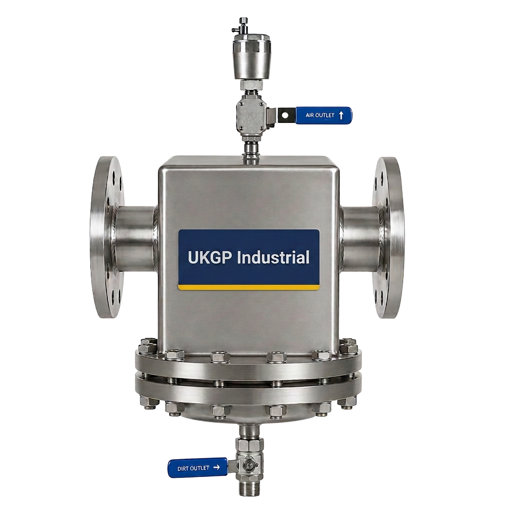
A sophisticated hydraulic separator often performs multiple roles, acting as a 4-in-1 device: hydraulic decoupler, air separator, dirt separator, and magnet. While a standard low loss header provides a basic zone for air and dirt to collect, dedicated separators often include internal baffles or PALL rings to aggressively remove microbubbles. This is a critical distinction in high-rise developments or systems with extensive pipe runs where entrained air can lead to localized cold spots and high noise levels. By forcing the water through a series of internal obstructions, the vessel breaks the surface tension of the microbubbles, allowing them to rise to the automatic air vent.
Similarly, for dirt separation, the reduction in velocity allows heavier magnetite and non-ferrous particles to drop to the base of the vessel. In systems following BSRIA BG50, managing these solids through a blow-down valve at the bottom of the separator is a mandatory maintenance task. While a dedicated side stream filtration unit is often recommended for total system health, having a primary collection point in the hydraulic separator provides an essential first line of defence for the boiler heat exchangers. This prevents the 'clogging' of the thin water-ways found in modern aluminium or stainless steel heat exchangers, which are highly susceptible to debris damage.
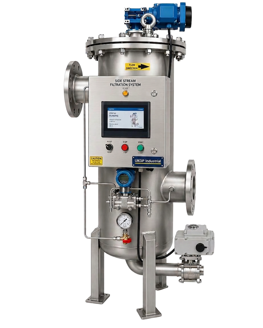
For clients managing large-scale assets, combining a hydraulic separator with a secondary side stream filtration system is the gold standard. While the separator handles the bulk of the hydraulic balance and heavy sediment, the side stream unit ensures that fine particles (down to 5 microns) are polished out of the system water. This dual approach significantly extends the life of the pumps and control valves. If your project requires high-performance water treatment components, UKGP Industrial can supply matching side-stream filtration skids alongside your header, ensuring a compatible and high-efficiency plant room package designed for longevity.
- Internal baffles facilitate microbubble coalescence and removal.
- Acts as a collection point for heavy sediment and magnetite.
- Compatible with BSRIA BG50 maintenance regimes.
- Reduces the load on secondary side stream filtration units.
Technical Compatibility: BSP vs Flanged PN16
Selecting the correct connection type for a hydraulic separator is a matter of both system pressure and installation speed. For smaller commercial units, typically up to 150 kW, BSP (British Standard Pipe) threaded connections are standard and offer a cost-effective, reliable joint. However, as the system capacity increases toward the 2000 kW mark, the mechanical stresses on the pipework and the weight of the water-filled vessel necessitate flanged connections, usually to PN16 standards. Flanged connections allow for easier removal and maintenance of the vessel or adjacent valves without needing to 'spin' the pipework, which is a major advantage for Facilities Managers (FMs).
UKGP Industrial ensures that all flanged units are manufactured to rigorous standards, mirroring the requirements set out for expansion bellows and other pressure-retaining components. The use of PN16 flanges provides a robust seal that can withstand the thermal expansion and contraction cycles typical of large LTHW (Low Temperature Hot Water) systems. When procurement leads are comparing quotes, the inclusion of the insulation jacket and the specific flange rating should be cross-referenced to ensure like-for-like quality. Our vessels are designed to integrate seamlessly into a plant room that may also utilize UKGP expansion bellows to manage pipework movement.
Furthermore, our lead time of 2-3 weeks for most commercial sizes ensures that contractors are not left waiting on-site during critical phase handovers. We understand that in the B2B sector, delivery reliability is as important as technical specification. Each unit is pressure tested prior to dispatch, ensuring that when it arrives on-site, it is ready for immediate integration into the system. With a 2-year warranty as standard, our separators and headers provide the commercial security required for large-scale government, healthcare, or private commercial developments where uptime is non-negotiable.
- BSP connections available for smaller systems (typically <150 kW).
- PN16 flanged connections for high-capacity 2000 kW systems.
- Eases maintenance and component replacement for FMs.
- Manufactured to resist thermal stress and pressure fluctuations.
Thermal Performance and Insulation Strategy
Energy efficiency in a plant room is often compromised by 'naked' vessels that radiate heat into the ambient air rather than delivering it to the building zones. A hydraulic separator has a large surface area, and without adequate insulation, it becomes a significant source of energy waste. This is why the UKGP low loss header range is supplied with a purpose-built insulation jacket. Not only does this improve the total system efficiency, but it also protects maintenance staff from burns and reduces the cooling load required for plant room ventilation. In modern building design, every kW saved contributes to the building's overall carbon reduction targets.
The jacket is typically removable, allowing for inspection of the vessel shell and the connection points during annual maintenance audits. This aligns with the proactive maintenance strategies outlined in CIBSE Guide M. When considering the hydraulic separator vs low loss header explained in this article, it is the attention to these 'finished' details that separates a basic component from a professionally engineered solution. Our jackets are designed to fit snugly around the vessel, including cut-outs for the vent and drain points, ensuring that there are no gaps where thermal bridging could occur.
For the procurement team, opting for a pre-insulated unit simplifies the supply chain. Rather than hiring a separate lagging contractor to finish the vessel on-site, the unit is delivered ready-clad. This further reduces on-site labour costs and ensures a professional, uniform finish across the plant room. When paired with our 40-2000 kW capacity range, these insulated headers provide a versatile solution for everything from school boiler rooms to massive district heating energy centres. Contact UKGP Industrial today for a competitive quote on our full range of hydraulic decoupling and air/dirt separation solutions.
- Pre-fitted insulation jackets reduce on-site labour and lagging costs.
- Improves plant room safety by limiting external surface temperatures.
- Key for meeting Part L energy efficiency requirements.
- Removable design allows for easy NDT or visual inspection.
Frequently asked questions
What is the main difference between a hydraulic separator and a low loss header?
- While the terms are often used interchangeably, a hydraulic separator is a precision-engineered vessel designed specifically for hydraulic decoupling, often including internal baffles for air and dirt removal. A low loss header is a type of hydraulic separator focused on creating a neutral pressure zone between primary and secondary circuits.
What kW range do UKGP low loss headers cover?
- Our range covers commercial applications from 40 kW up to 2000 kW, making them suitable for everything from small commercial units to large-scale industrial heating systems.
Do these units come with a warranty?
- Yes, all UKGP low loss headers and hydraulic separators come with a 2-year warranty and a standard lead time of 2-3 weeks.
Can I get a flanged version for a high-pressure system?
- Absolutely. We offer both BSP threaded connections for smaller systems and PN16 flanged connections for larger, higher-capacity commercial installations.
Are the vessels insulated?
- Yes, each unit is supplied with a high-quality, removable insulation jacket to ensure energy efficiency and compliance with building regulations regarding heat loss.