The Essential Tool Kit for Field Calibration
Before commencing calibration in a plant room or process area, an engineer must ensure all consumables are within their expiry dates. Buffer solutions are chemically sensitive; pH 10 buffers, in particular, degrade rapidly when exposed to atmospheric CO2. Always use fresh aliquots of buffer for every calibration event rather than dipping sensors directly into the primary supply bottle, which risks cross-contamination.
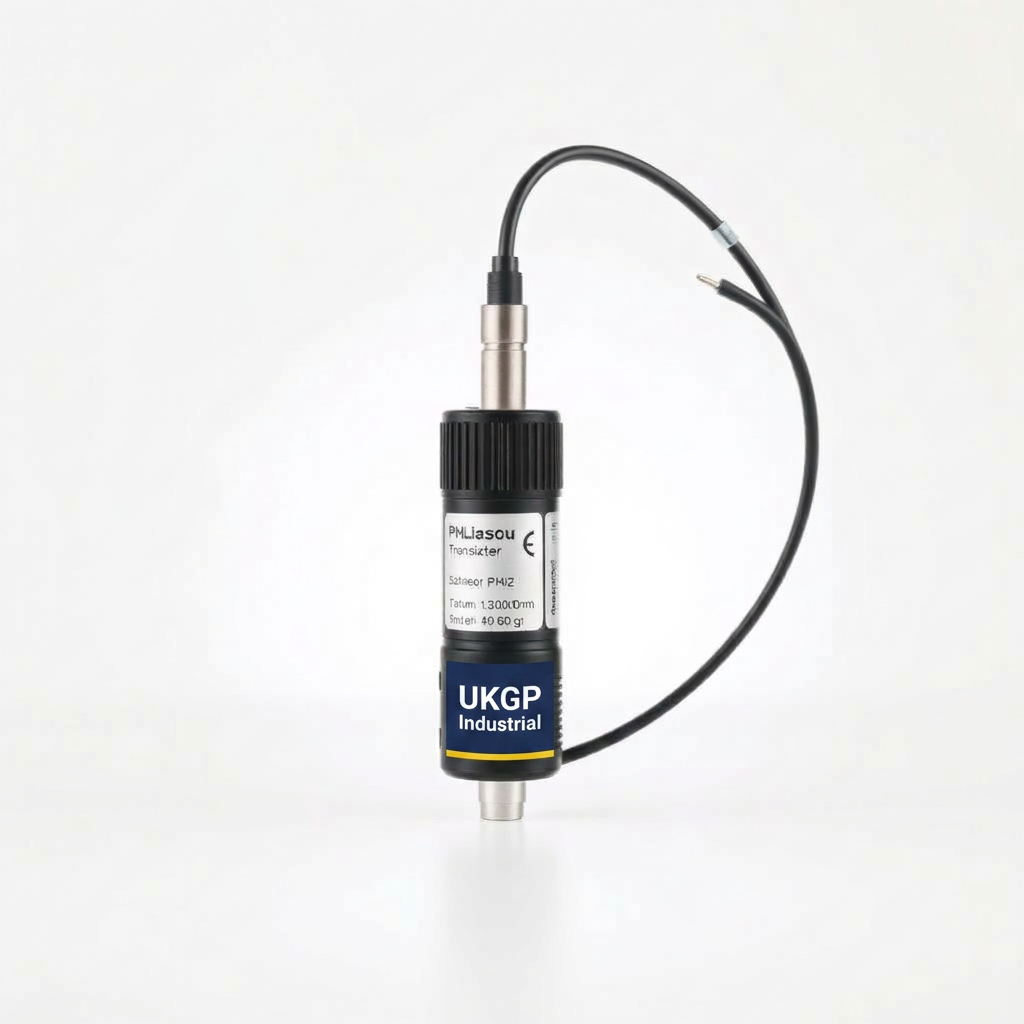
The shift toward smart pH sensor transmitters with M12 quick-connectors has simplified the hardware requirements. Unlike older pot-and-dial transmitters, these digital systems store calibration data within the sensor head itself. This allows for 'hot-swapping' pre-calibrated sensors or using a digital interface to perform calibration without disturbing the 4-20mA loop wiring. Ensure your digital interface is compatible with the sensor's proprietary protocol if it is not a standard MODBUS or HART system.
Temperature compensation is the most overlooked factor in field calibration. Because the Nernstian slope of a pH electrode changes with temperature, you must have an integrated or external Pt100/Pt1000 RTD sensor. Ensure your buffer solutions have reached the same ambient temperature as the process water or the calibration environment to avoid thermal lag errors during the slope calculation.
- pH buffer solutions (NIST traceable) typically 4.01, 7.00, and 10.01.
- Deionised or distilled water for intermediate rinsing.
- Lint-free industrial wipes (non-abrasive).
- Clean glass or plastic beakers for buffers.
- M12 connector interface or handheld programmer for smart transmitters.
Sensor Removal and Initial Inspection
In high-pressure systems or busy plant rooms, safety is paramount. Before removing a pH sensor, the line must be isolated and depressurised. Many industrial sensors are mounted in 'T-piece' flow cells or immersion probes; these should be equipped with isolation valves. If the sensor is removed while the line is under pressure, the sudden discharge of water or chemical media poses a significant risk to the engineer and local electrical equipment.
Once removed, the sensor tip should be inspected for physical fouling. In heating and cooling loops, it is common to find coatings of magnetite, calcium carbonate, or biofilm. These must be removed before calibration. If the glass bulb or the reference junction (often a porous PTFE or ceramic ring) is coated, the sensor will exhibit a slow response or 'drift,' making calibration impossible. Heavy scale should be dissolved using a weak 5% Hydrochloric acid solution, followed by a thorough rinse in deionised water.
Check the M12 connector for signs of moisture or corrosion. One of the primary advantages of modern industrial pH sensor transmitters is the robustness of the M12 interface compared to the old S7 or BNC connectors. However, if the O-rings on the connector have failed, signal integrity will be compromised. A quick wipe with an electronics cleaner is good practice before reassembly.
- Isolate the sensor from the main flow using bypass valves.
- Depressurise the sensor housing slowly to avoid glass bulb breakage.
- Carefully unscrew the sensor, noting any excessive force required (indicating scale).
- Disconnect the M12 cable, ensuring the pins remain dry and clean.
Step-by-Step Two-Point Calibration Procedure
The standard for industrial water treatment is the two-point calibration. The first point is almost always pH 7.00, known as the Zero Point or Offset. Rinse the sensor in deionised water, blot it dry with a lint-free wipe—do not rub, as this creates static charge on the glass—and immerse it in the pH 7.00 buffer. Allow the reading to stabilise. In modern smart systems, the transmitter will automatically recognise the buffer value and wait for a stable millivolt signal.
After the pH 7.00 point is accepted, repeat the rinse and dry process before immersing the sensor in the second buffer. For most chilled water and heating systems (which are typically alkaline), pH 10.01 is the correct second point. For wastewater or acidic processes, pH 4.01 is used. The transmitter now calculates the 'Slope.' In a perfect world, this would be 59.16 mV per pH unit at 25°C. The transmitter converts this to a percentage efficiency. Any slope falling below 85% is a clear indicator that the electrode is reaching its end of life.
The integration of M12 smart electronics in our industrial pH sensor transmitters allows for this data to be stored on the sensor chip. This means the calibration follows the sensor. If you calibrate a sensor in a workshop and then take it to the plant room, the transmitter head will read the new calibration constants immediately upon connection. and provide a precise 4-20mA or RS485 output based on those updated parameters.
- pH 7.00 Zero Point: Establishes the 'Isopotential' point where mV = 0.
- pH 4.01/10.01 Slope: Calculates the efficiency (mV per pH unit).
- Stability Criteria: Smart transmitters usually 'lock' the reading once the mV delta is below 0.5mV/min.
Interpreting Calibration Data and Sensor Health
A successful calibration is not just about the transmitter showing the correct number; it is about the health of the electrode. The 'Offset' value indicates the state of the reference electrode. If the offset is greater than 30mV, the reference electrolyte may be contaminated or depleted. This is common in systems where 'poisoning' ions like sulphides or heavy metals are present, which react with the silver/silver-chloride reference wire.
The 'Slope' value reflects the responsiveness of the glass measuring electrode. As the glass ages or becomes dehydrated, its ability to exchange hydrogen ions decreases, leading to a shallow slope. If the slope is exceptionally high (over 105%), it often indicates contaminated buffer solutions or a failure in the temperature compensation circuit. Monitoring these two parameters weekly allows facilities managers to predict failure rather than reacting to it.
In closed-loop systems following BSRIA BG50 guidelines, maintaining a stable pH is vital for the efficacy of corrosion inhibitors like molybdates or nitrites. If your slope is drifting significantly between calibrations, it could be a sign that the inhibitors are coating the sensor, or that there is an undiagnosed leak in the system causing constant fresh-water make-up, which alters the chemistry and stresses the sensor.
- Offset: Should be between -30mV and +30mV.
- Slope: Should be between 85% and 105%.
- Response Time: Sensor should reach 95% value within 30 seconds.
In-Situ vs. Laboratory Calibration
There is a technical debate regarding whether to calibrate pH sensors in a controlled workshop environment or in-situ at the plant room. Workshop calibration offers stable temperatures and clean conditions, which are ideal for high-precision digital transmitters. With M12 quick-connect electronics, a technician can bring the sensor back to the bench, calibrate it, and return it to the line. This is often the preferred method for systems utilizing side-stream filtration units where access might be cramped.
In-situ calibration, however, accounts for the actual electrical environment of the plant. Significant 'ground loops' or stray currents in industrial piping can sometimes shift a pH reading. If a sensor is calibrated on a bench but reads differently when installed in a stainless steel pipework, an in-situ 'process calibration' (a single-point offset adjustment while the sensor is in the process) may be required to align the sensor with a verified handheld dip-test.
Regardless of the location, the use of side-stream filtration loops for pH sensing is highly recommended. By diverting a small flow of process water through a dedicated sampling manifold, the sensor is protected from the high velocities and debris found in the main headers. This not only extends the life of the pH sensor but also makes the calibration process significantly safer and more accessible for the maintenance team.
- Pre-calibration: Done in the lab to verify new sensor integrity.
- Field-calibration: Done in-situ to account for actual process conditions.
- Verification: Checking the sensor against a third-party handheld meter.
Troubleshooting Common Calibration Errors triumphs
If a sensor refuses to calibrate, the first thing to check is the reference junction. If the junction is blocked, the electrical circuit between the internal reference and the external process is broken. This often results in a reading that 'wanders' aimlessly on the transmitter display. For sensors with a liquid junction, ensuring the electrolyte is topped up is key; for the more common industrial 'solid-gel' sensors, a soak in warm water or a cleaning solution may clear the blockage.
Signal noise is an often-overlooked issue in modern plant rooms. Variable Speed Drives (VSDs) on pumps can induce high-frequency noise into the 4-20mA signal lines. While digital pH sensor transmitters with M12 connectors are much more resistant to this than older high-impedance analogue cables, the cable shielding must still be correctly grounded at the controller end. If the pH reading jumps sporadically when a pump starts, electrical interference is the likely culprit.
Dehydration of the glass bulb occurs if the sensor is left in a dry pipe for an extended period. pH sensors must always remain wet. If a system is drained for seasonal maintenance, the sensor should be removed and stored in a soaking cap filled with 3M KCl (Potassium Chloride) solution. If the sensor has dried out, it may be revived by soaking it for 24 hours in KCl, but the slope will likely be permanently affected.
- Reference junction clogging.
- Glass bulb dehydration.
- Temperature compensation failure.
- Signal noise from variable speed drives (VSDs).
Regulatory Compliance and Record Keeping落
For UK building services engineers, calibration is not just a maintenance task; it is a compliance requirement. BSRIA BG50 highlights the importance of keeping 'logbooks' of all water quality parameters. A digital transmitter that logs calibration dates and sensor health (slope/offset) provides an audit trail that is invaluable during cooling tower inspections by the HSE or during insurance audits of high-value HVAC assets.
When calibrating, always record the 'As Found' and 'As Left' values. This data allows you to perform trend analysis. If the 'As Found' value is consistently diverging from the expected process value by more than 0.2 pH, your calibration frequency is likely too low, or there is an issue with the chemical dosing pumps over-shooting their targets. Accurate pH control is the first line of defence against the pitting corrosion that leads to premature pipework failure.
Finally, ensure that all buffer solutions are traceable to National Standards (NIST). Cheap, non-certified buffers can have a variance of +/- 0.05 pH or more, which is compounded by temperature errors. In critical applications like steam boiler feed-water, where pH is maintained in a very narrow band to protect the economiser, only high-grade certified buffers should be used to ensure the transmitter's calibration is legally and technically defensible.
- BSRIA BG29/21: Pre-commission cleaning and water quality.
- BSRIA BG50: Water treatment for closed heating and cooling systems.
- BS EN 12502: Protection of metallic materials against corrosion.
Conclusion: Maximising Sensor Longevity
The precision of a pH control system is the product of both high-quality hardware and rigorous maintenance protocols. By moving to digital M12 pH sensor transmitters, UK engineers can significantly reduce the 'dark time' associated with sensor failure and calibration drift. These smart systems provide the transparency needed to move from reactive maintenance to a predictive, data-driven approach, ensuring that heating and cooling systems operate at peak efficiency.
Effective calibration is as much about the process as it is the result. Cleaning the sensor correctly, using fresh NIST-traceable buffers, and understanding the significance of slope and offset values will extend the life of your sensors and protect the integrity of your building's primary plant. In the context of rising energy costs and the drive for carbon reduction, the role of precise water chemistry—managed by accurate pH sensing—has never been more critical.
For those managing complex sites, standardising on a single transmitter and sensor platform can simplify the training of site staff and reduce the inventory of spare parts. By following the technical steps outlined in this guide, you ensure that your pH monitoring system remains a reliable tool for asset protection and regulatory compliance.
- Always use fresh buffers and rinse between steps.
- Perform two-point calibration to monitor sensor health (slope).
- Utilise digital M12 transmitters to eliminate signal noise.
- Maintain a calibration log for BSRIA/HSE compliance.
Frequently asked questions
How often should industrial pH sensors be calibrated?
- Monthly calibration is standard for most industrial cooling and heating loops. However, if the process involves high temperatures or aggressive chemical dosing, weekly checks may be necessary to counter sensor drift.
Can I calibrate using only one buffer solution?
- No. Always calibrate with a minimum of two points (usually pH 7.0 and 4.0 or 10.0) to establish the slope of the electrode. Single-point calibration only adjusts the offset and cannot account for sensor aging.
What does the slope percentage signify during calibration?
- The 'slope' represents the efficiency of the electrode. A perfect sensor has a slope of 100% (59.16 mV/pH at 25°C). If the transmitter reports a slope below 85% or an offset greater than +/- 30mV, the sensor is nearing its end-of-life and requires replacement.
Which buffer solutions should I use for BSRIA compliant systems?
- Standard buffers are usually 4.0, 7.0, and 10.0. For closed-loop heating systems (BSRIA BG29/21) where pH is typically 9.0–10.5, using 7.0 and 10.0 is traditional. For acidic process water, 4.0 and 7.0 should be used.