The Fundamental Electrochemistry of pH Measurement
At its core, a pH sensor is an electrochemical galvanic cell. It operates based on the Nernst Equation, which defines the relationship between the concentration of hydrogen ions (H+) in a solution and the electrical potential generated across a sensing membrane. In industrial applications, this is typically achieved using a ‘combination electrode’ which houses both the sensing and reference elements within a single 12mm or 3/4" NPT body.
The sensing element consists of a thin, ion-sensitive glass bulb. When immersed in a liquid, a hydrated layer forms on both the inner and outer surfaces of this glass. The potential difference developed across this membrane is proportional to the difference in hydrogen ion activity between the internal buffer solution (usually pH 7) and the external process fluid. Because this potential is measured in millivolts (mV), the signal is extremely susceptible to electrical noise and requires high-impedance amplification.
The reference electrode completes the circuit. It is designed to maintain a constant potential regardless of the pH of the liquid. This is achieved by using a silver/silver chloride (Ag/AgCl) wire immersed in a potassium chloride (KCl) electrolyte. The junction—a porous ceramic or PTFE wick—allows a minute amount of electrolyte to leak into the process, establishing an electrical bridge. Any compromise in this junction, such as fouling or 'poisoning' by process chemicals, is a primary cause of sensor failure in industrial systems.
- The Glass Electrode: A hydrogen-ion sensitive bulb.
- The Reference Electrode: Provides a stable, known voltage.
- The Electrolyte/Junction: Facilitates electrical continuity with the process fluid.
- The Transmitter: Converts high-impedance millivolt signals into a linear 4-20mA or digital output.
Understanding the Millivolt Signal and Slope
The relationship between pH and the voltage produced by the sensor is linear. Theoretically, at 25°C, a pH sensor produces a change of 59.16 mV for every unit change in pH. This value is known as the 'slope'. A perfectly functioning sensor at pH 7.0 (neutral) should produce 0 mV. As the solution becomes more acidic, the voltage increases positively; as it becomes more alkaline, the voltage moves into the negative range.
In practice, no sensor is perfect. 'Offset' refers to the deviation from 0 mV at pH 7, while 'slope efficiency' refers to how closely the sensor matches the theoretical 59.16 mV/pH output. Over time, as the glass membrane ages or becomes coated, the slope efficiency drops. Industrial transmitters compensate for this through calibration, but once the slope falls below roughly 80% (approx. 47 mV/pH), the sensor is considered 'spent' and must be replaced to ensure system accuracy.
It is critical for M&E contractors to realise that this millivolt signal is high-impedance. Prior to the advent of smart transmitters, this required specialized low-noise coaxial cables which could not be easily shortened or extended without signal degradation. Modern systems solve this by digitising the signal as close to the sensor as possible.
- -59.16 mV per pH unit at 25°C.
- 0 mV at neutral pH 7.0.
- Positive mV in acidic conditions (<7 pH).
- Negative mV in alkaline conditions (>7 pH).
Integral Temperature Compensation (ATC)
Temperature has a two-fold effect on pH measurement. Firstly, the chemical equilibrium of the solution itself changes with temperature. Secondly, and more importantly for the sensor, the Nernstian slope is temperature-dependent. As the temperature of the process fluid rises, the millivolt output per pH unit also increases. For example, at 0°C the slope is roughly 54 mV/pH, whereas at 100°C it rises to approximately 74 mV/pH.
Without Automatic Temperature Compensation (ATC), a pH reading taken in a 60°C LTHW (Low Temperature Hot Water) circuit using a transmitter calibrated at 25°C would be significantly inaccurate. Industrial pH sensor transmitters almost always incorporate an internal Pt100 or Pt1000 RTD (Resistance Temperature Detector) within the sensor body. This allows the transmitter’s microprocessor to calculate the corrected pH value in real-time.
For engineers designing plant-room controls, ensuring that the pH transmitter is receiving an accurate temperature feed from the sensor is vital. In systems with high thermal fluctuation, such as beverage processing or variable-load cooling towers, the speed of the temperature sensor's response can be just as important as the pH response itself to prevent 'saw-tooth' data patterns in the BMS (Building Management System).
Smart Electronics and M12 Quick-Connect Integration
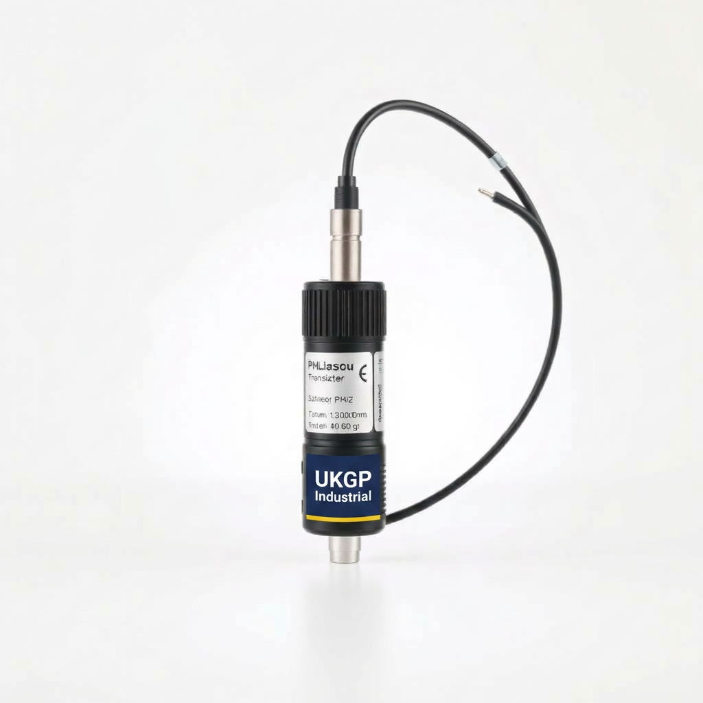
In traditional industrial installations, pH sensors were wired directly into a transmitter or controller using fixed cables. This presented a significant maintenance hurdle: when a sensor failed, a technician had to de-wire the unit from the terminal rail, often in cramped or wet conditions. The introduction of M12 quick-connect electronics has transformed this process, particularly for UKGP Industrial pH sensor transmitters.
The M12 connector allows for a 'plug-and-play' approach. The transmitter remains fixed and wired to the PLC or BMS via a standard 4-20mA loop, while the sensor can be detached and replaced in seconds. This is particularly advantageous for BSRIA-compliant water treatment regimes where regular calibration is mandated. Sensors can be pre-calibrated in a laboratory environment and then swapped into the field, ensuring the highest possible accuracy without the need for portable buffer solutions on-site.
Furthermore, 'smart' electronics within the transmitter head can store calibration data, serial numbers, and diagnostic info. This eliminates the 'drift' associated with long analog cable runs. If the transmitter is located 20 metres from the sensing point (e.g., in a large central plant room), the digital or amplified signal is immune to the electromagnetic interference (EMI) typically generated by nearby pumps, VSDs, and heavy-duty switchgear.
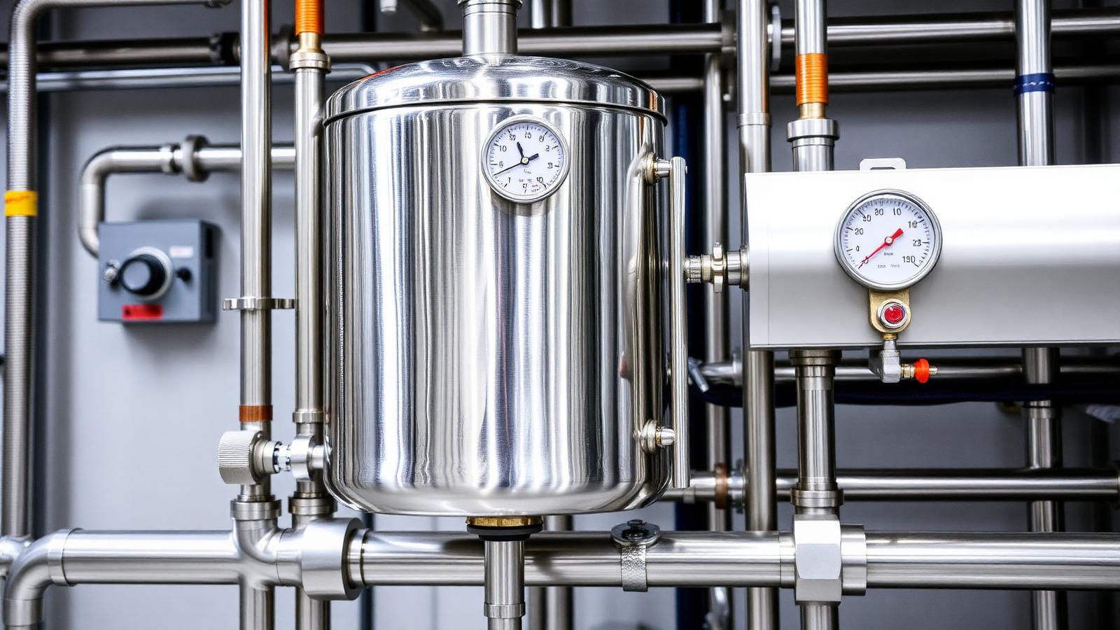
Application: Cooling Towers and Evaporative Condensers
Cooling towers are among the most demanding environments for pH sensors. As water evaporates, the concentration of dissolved solids increases, and the pH typically rises due to the stripping of CO2. If the pH exceeds the saturation point of calcium carbonate, scaling occurs on the heat exchanger surfaces, drastically reducing thermal efficiency and increasing the risk of Legionella proliferation in bio-films.
Conversely, if the pH drops—potentially due to acidic rain or the over-dosing of biocides—the water becomes corrosive to the galvanised steel or copper components of the cooling circuit. Sensors in these applications must be robust enough to withstand constant flow and potential biological fouling. A pH sensor transmitter with a flat-surface glass electrode is often preferred here, as the flow of water across the flat face provides a 'self-cleaning' action, reducing the frequency of manual maintenance.
Integration with the blowdown valve is the primary control objective. The pH transmitter provides the signal to the controller which, upon reaching a set point (typically pH 8.5 to 9.0 in many UK systems), opens the blowdown valve to bleed off high-alkalinity water and replaces it with fresh make-up water. This control loop is essential for maintaining the 'Cycles of Concentration' within safe limits.
Application: Wastewater and Trade Effluent Compliance
Industrial facilities in the UK are bound by strict 'Consent to Discharge' agreements with water authorities. These agreements typically specify a pH range (often between 6.0 and 10.0) for any wastewater entering the public sewer. Failure to comply can lead to significant fines and environmental prosecution. pH sensor transmitters are the first line of defence in these effluent monitoring stations.
In many wastewater applications, the fluid contains suspended solids, oils, and fats which can quickly coat a standard bulb sensor. Here, the use of side-stream filtration or specialized 'tuff-tip' sensors is recommended. By pulling a representative sample into a side-stream loop, the sensor is protected from the harshest turbulence and debris while still providing real-time data for neutralising acid/alkaline dosing pumps.
The transmitter’s 4-20mA output is usually logged for regulatory reporting. For facilities managers, the ability to view these trends over time allows for the identification of process upsets—such as a chemical spill or a failure in a neutralisation tank—before the effluent leaves the site. High and low alarms are mandatory, often interlocked with an emergency shut-off valve to prevent non-compliant discharge.
Installation Best Practices for M&E Contractors
Correct physical installation is non-negotiable for sensor longevity. A pH sensor must always be installed at an angle—at least 15 degrees above the horizontal. This ensures that the internal bubble within the glass electrode stays at the top, keeping the sensing membrane and the internal reference junction fully wetted. Installing a sensor vertically upwards or completely horizontal can lead to air pockets and erratic readings.
Flow velocity is another critical factor. Ideally, the sensor should be placed in a location with a steady, non-turbulent flow. In high-pressure lines, the use of a bypass or 'sample manfold' is advisable. This allows the sensor to be isolated for calibration without shutting down the entire main line. UKGP Industrial sensor housings are designed to handle typical plant-room pressures, but engineers must check that the maximum pressure/temperature rating of the sensor body exceeds the system's relief valve setting.
Cable management is often overlooked. Even with M12 connectors, signal cables should not be run parallel to high-voltage power lines. Using shielded twisted-pair cable for the 4-20mA loop and ensuring the shield is grounded at only one end (typically the controller end) prevents ground loops that can offset the pH reading by several units.
Maintenance and Calibration Strategy (BG50 Compliance)
BSRIA BG50 (Water treatment for closed heating and cooling systems) emphasises the importance of consistent monitoring. For pH sensors, this means a rigorous calibration schedule. A 'two-point' calibration is the industry standard: typically using pH 7.0 buffer to set the offset and pH 4.0 or 10.0 buffer to set the slope.
Cleaning is a prerequisite for calibration. Sensors should be cleaned with a soft cloth and a mild detergent or, in the case of calcium scaling, a weak 5% Hydrochloric Acid (HCl) solution. Never use sharp objects to scrape the glass, as micro-scratches will provide sites for further fouling and eventual cracking. After cleaning, the sensor must be rinsed thoroughly with deionised water before being placed in the buffer solution.
Facilities managers should keep a 'calibration log'. A declining slope efficiency is a predictable indicator of sensor life. By tracking this, maintenance teams can move from 'reactive' replacement (waiting for the sensor to fail) to 'predictive' maintenance, ordering replacement M12 sensor heads before the system's chemistry drifts out of specification. This proactive approach is the cornerstone of modern, high-availability building services.
Frequently asked questions
How often should an industrial pH sensor be calibrated?
- Industrial pH sensors should generally be calibrated every 30 to 90 days, depending on the severity of the process. In high-temperature or high-fouling environments like cooling towers, monthly calibration is recommended to account for electrode drift.
Can pH sensors be stored dry?
- No. pH sensors must remain 'wet'. If the reference junction dries out, the salt bridge is destroyed, and the sensor will fail. Always use a storage solution (typically 3.0 M KCl) and never store in deionised water.
What is the maximum temperature for a standard pH sensor?
- Standard pH electrodes are typically rated up to 60°C or 80°C. For steam condensate or high-temperature process loops, specialised high-temperature glass and pressurised reference junctions are required to prevent electrolyte boiling.
What are the benefits of M12 quick-connect electronics?
- M12 connectors facilitate rapid 'hot-swapping' of sensors without rewiring the transmitter. This reduces downtime, eliminates wiring errors in damp plant-room environments, and allows for 'lab-calibration' where sensors are calibrated in a clean environment before being deployed to the field.