The fundamental role of expansion joints
Expansion joints, often colloquially termed bellows, are flexible elements integrated into piping systems to manage thermal growth, mechanical vibration, and structural settlement. In the UK, the design of these systems is governed by BS EN 14917 for metal bellows and various ISO standards for elastomeric equivalents. Without adequate flexibility, the stresses generated by a 50-metre run of carbon steel pipe heated from 10°C to 80°C would exceed the yield strength of the material, leading to catastrophic failure at fixed points or elbows.
The selection process begins with a movement analysis. Engineers must calculate the total linear expansion using the coefficient of thermal expansion for the specific pipe material—typically 0.012 mm/m/°C for carbon steel and 0.017 mm/m/°C for stainless steel. Once the growth is quantified, the system must be divided into manageable sections using main anchors, with expansion bellows placed between them to neutralise the movement.
Beyond thermal movement, bellows serve as critical vibration isolators. Reciprocating pumps and centrifugal chillers generate cyclic loads that can cause fatigue in rigid pipework. Rubber bellows, with their inherent damping properties, are particularly effective at absorbing these high-frequency vibrations, whereas metal bellows are often preferred for higher pressure and temperature applications where rubber would degrade.
- Absorption of axial thermal expansion (compression and extension).
- Isolation of high-frequency vibration from pumps and chillers.
- Compensation for minor pipework misalignment.
- Reduction of noise transmission through the pipe wall.
Axial expansion bellows: Principles and application
Axial bellows are the most common type of expansion joint in UK HVAC installations. They are designed to accommodate movement purely along the longitudinal axis of the pipe. The bellows constant, or spring rate, determines the force required to compress the unit, but the more significant force is 'pressure thrust.' This is the force exerted by the internal pressure on the cross-sectional area of the bellows, which acts to push the bellows open. Improper anchoring in axial systems is the primary cause of site failures during pressure testing.
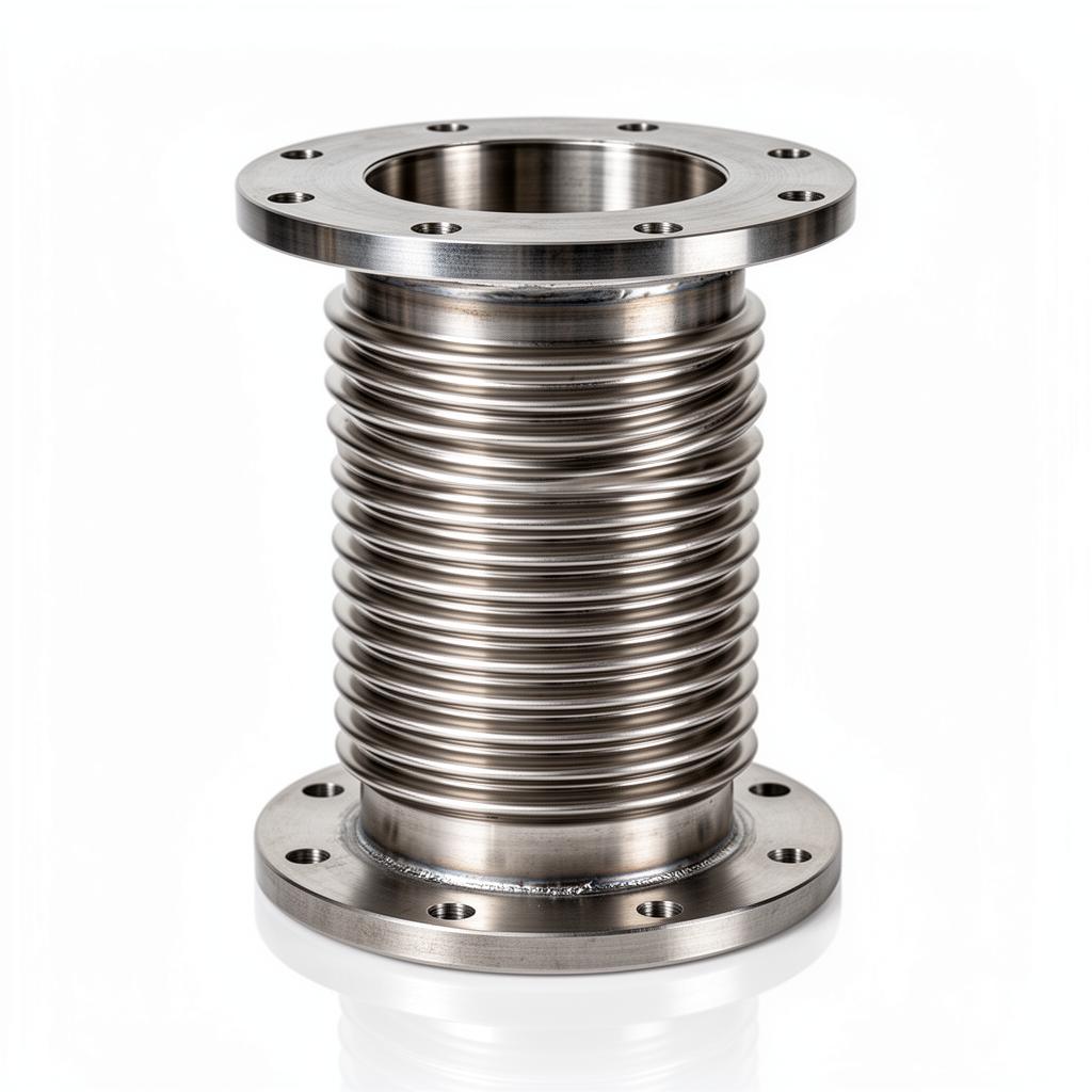
These units are typically constructed from multi-ply stainless steel (Grade 316L or 321) to provide a balance between flexibility and pressure resistance. In LTHW or MTHW systems, they are often supplied with internal telescopic sleeves to provide a smooth flow path, reducing turbulence and preventing the 'whistling' effect associated with high-velocity fluids passing over the convolutions.
Installation of axial bellows requires strict adherence to guiding specifications. According to EJMA (Expansion Joint Manufacturers Association) standards, the first pipe guide must be located within four pipe diameters of the bellows, and the second within fourteen. This prevents the pipe from bowing or 'squirming' under the influence of pressure thrust, ensuring the movement remains purely axial.
- Simple installation and low capital cost.
- Requires robust pipe guiding to prevent squirm.
- Internal liners recommended for high-velocity media.
- Available with flanged or butt-weld ends to BS EN 1092-1.
Lateral and universal expansion joints
Lateral expansion joints are designed to accommodate movement perpendicular to the pipe axis. Unlike simple axial joints, lateral units are usually 'tied'—equipped with tie bars that restrain the pressure thrust. Because the tie bars carry the internal pressure load, the anchors at the ends of the pipe run only need to withstand the force required to deflect the bellows. This significantly reduces the structural requirements for the building's steelwork.
A universal expansion joint consists of two bellows joined by a centre spool piece. This configuration allows for much larger lateral offsets than a single bellows. In UK district heating schemes or large industrial complexes where pipe runs may cross building expansion joints, universal bellows are essential for managing three-dimensional movement. They can absorb axial, lateral, and angular movements simultaneously, though their primary strength lies in high-offset lateral compensation.
When specifying lateral joints, the engineer must consider the 'planar' nature of the movement. A standard two-tie-bar arrangement allows movement in only one plane. If movement is expected in multiple planes, a gimbal or a four-tie-bar arrangement with spherical washers may be required. This level of detail is vital in congested plant rooms where pipework often snakes around structural columns and other services.
- Tied lateral constraints eliminate pressure thrust on anchors.
- Ideal for multi-plane movements in complex plant rooms.
- Reduces the complexity of main anchor design.
- Can be supplied as 'universal' joints with two bellows in series.
Angular and gimbal expansion joints
Angular expansion joints, or 'hinged' bellows, are designed to permit rotation in a single plane. They are used in sets of two or three to absorb movement in a 'Z' or 'L' shaped offset. The hinge mechanism serves two purposes: it prevents axial movement (restraining pressure thrust) and ensures the bellows convolutions open and close in a uniform, controlled arc. This mechanical restraint makes them incredibly robust for high-pressure steam applications.
Gimbal joints are a sophisticated evolution of the hinged joint. They incorporate two sets of hinges at right angles to one another, allowing the joint to rotate in any plane. This is particularly useful in systems where the thermal expansion of a vertical riser must be absorbed by a horizontal branch that is also moving. By using a pair of gimbal joints, the system can accommodate complex 3D thermal growth without transferring pressure thrust to the connected equipment.
The design of these units must comply with EN 14917, ensuring that the hinge pins and gimbal rings are calculated to withstand the massive forces generated by internal pressure. In a 300mm pipe at 10 bar, the pressure thrust can exceed 7 tonnes; the hinge assembly must manage this load while remaining flexible enough to rotate under thermal stress.
- Gimbal joints allow for multi-plane angular rotation.
- Used in pairs to absorb large lateral displacements in 'Z' bends.
- Hinge pins must be sized to carry the full pressure thrust.
- Commonly used in high-pressure steam and process applications.
Rubber bellows: Material selection and limits
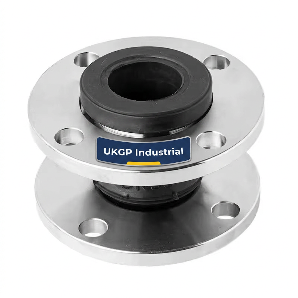
Rubber expansion bellows (or 'pump bellows') are the workhorses of the UK HVAC industry, particularly for chilled water and LTHW systems. They are typically constructed from EPDM or Nitrile with synthetic internal reinforcement (such as Kevlar or Nylon cord). Their primary advantage is the ability to absorb noise and vibration across a broad frequency spectrum, making them ideal for connecting pumps to rigid headers.
Materials must be selected based on the media. EPDM is suitable for water and dilute acids but will swell and fail if exposed to oils or hydrocarbons. For systems containing oil-line trace elements or compressed air with lubricants, Nitrile (NBR) membranes are mandatory. For domestic hot water (DHW) services, engineers must specify WRAS-approved EPDM to ensure compliance with UK potable water regulations.
Unlike metal bellows, rubber bellows have a non-linear relationship between temperature and pressure. As the temperature rises, the maximum allowable working pressure (MAWP) of the rubber decreases. A bellows rated at 16 bar at 20°C may only be rated for 6-8 bar at 90°C. Engineers must refer to the manufacturer's de-rating tables to ensure the unit is suitable for the peak operating conditions of the plant. Units should also be fitted with control units (tie bars) if the system pressure exceeds certain thresholds or if the anchors are not sufficiently rigid.
- Excellent vibration damping for pump connections.
- Resistance to chemicals and galvanic corrosion.
- Lower pressure/temperature limits compared to metal (typically 16 bar @ 90°C).
- No internal liner required for most standard HVAC velocities.
Flange specifications and installation standards
In the UK, the majority of expansion bellows are supplied with flanged ends, conforming to BS EN 1092-1 (formerly BS 4504). PN16 is the standard rating for most HVAC applications, though PN25 or PN40 may be required for high-rise buildings or high-pressure steam. It is critical to ensure that the bellows flange rating matches the mating pipework flange; a PN16 bellows cannot be safely bolted to a PN25 flange due to differences in bolt circle diameters and hole counts.
One common issue on site is the over-torquing of rubber bellows flanges. Most rubber units feature a 'swivel' or 'van stone' flange that sits behind a raised rubber face. The seal is created by the compression of the rubber against the mating flange, not by a separate gasket. Over-tightening can cut the rubber face or distort the flange, leading to leaks. Torque should be applied in a star pattern to the values specified by the manufacturer.
For stainless steel bellows, flanges may be fixed (welded) or loose (van stone). Loose flanges facilitate easier installation as the bolt holes can be aligned without twisting the bellows membrane. Torsional stress is the 'silent killer' of metal bellows; even a few degrees of twist during installation can cause the convolutions to fatigue and crack within weeks of commissioning.
- Compliance with BS EN 1092-1 for flange dimensions and ratings.
- Verification of 'all-in-one' vs. 'loose' flange designs.
- Importance of correctly torquing bolts to prevent flange distortion.
- Material compatibility between pipe flanges and bellows flanges.
Commissioning and BSRIA guidelines
The commissioning phase is often when expansion joints are most vulnerable. BSRIA BG29/21 specifies rigorous flushing and chemical cleaning procedures to remove scale and debris. During these high-velocity flushes, particulate matter can become trapped in the convolutions of a bellows, particularly those without internal liners. This can cause local erosion or 'packing' of the bellows, which prevents it from compressing correctly when the system is brought up to temperature.
Before the system is filled, it is vital to check that all shipping pins or 'pull-bars' have been removed. These are painted in high-visibility colours (usually yellow or red) and are intended to keep the bellows at its neutral length during transport and installation. If left in place, the bellows cannot move, and the resulting thermal expansion will transfer directly to the anchors or the bellows itself, often leading to immediate failure of the pipe supports.
Finally, engineers should ensure that the system is properly 'cold-set' if required by the design. Cold-setting involves pre-stretching the bellows during installation so that it sits in its neutral, unstressed state when at its mean operating temperature. This technique allows a single bellows to manage a larger range of movement than if it were simply installed at its 'free' length.
- BSRIA BG29/21 guidelines for system cleanliness and protection.
- Pre-commissioning cleaning risks to bellows membranes.
- Importance of temporary 'dead-weights' or lock-bars during shipping.
- Post-installation inspection checklists.
Maintenance and failure mode analysis Necropsy
Maintenance of expansion bellows is largely a visual process, but it is a critical component of a facilities management regime. For metal bellows, the primary concern is Stress Corrosion Cracking (SCC), often caused by the presence of chlorides in the water or the external environment. If the water treatment is not managed in accordance with BSRIA BG50, the highly stressed convolutions of a 304 or 316L bellows can fail rapidly. External pitting is also common if the joints are located in a coastal or industrial environment without protective coatings.
Rubber bellows exhibit different failure modes. Over time, the elastomer will lose its plasticisers, leading to hardening or 'alligatoring' of the surface. This is exacerbated by high temperatures or exposure to UV light if the plant room is not correctly shaded. A 'hard' rubber bellows has lost its ability to absorb vibration and must be replaced. Any sign of bulging or reinforcement ply exposure is an indication of imminent failure and requires immediate isolation of the system.
When a bellows fails, a 'necropsy' or forensic analysis should be performed. Was the failure due to fatigue (indicated by circumferential cracks), over-pressure (indicated by deformed convolutions), or corrosion? Understanding the root cause ensures that the replacement unit is specified with the correct materials or protective features, such as a different grade of stainless steel or the addition of a shroud.
- Visual inspection for convolution deformation or 'squirm'.
- Identifying signs of stress corrosion cracking (SCC) in stainless steel.
- Monitoring for rubber hardening or 'alligatoring' due to UV/Heat.
- The role of BG50 in ongoing water treatment and bellows life.
Frequently asked questions
Can an axial expansion joint accommodate lateral offset?
- Axial bellows are designed for movement along the pipe axis only. If lateral displacement is present beyond 1-2mm, the convolutions will distort unevenly, leading to premature fatigue and eventual shearing of the bellows membrane. Lateral or universal joints must be used instead.
When are internal sleeves and external shrouds required?
- Internal sleeves (liners) mitigate the risk of flow-induced vibration and erosion in high-velocity systems (typically over 6m/s for water or 12m/s for steam) and protect the convolutions from particulate build-up. External shrouds protect the delicate membrane from mechanical damage and weld splatter.
What are the safety considerations during pressure testing?
- Pressure testing should never exceed 1.5 times the design pressure. It is critical that the pipework is fully anchored and guided before testing; otherwise, the pressure thrust will extend the bellows beyond its design limit, causing permanent deformation or catastrophic failure.
How do I choose between EPDM and Nitrile rubber membranes?
- EPDM is standard for LTHW and chilled water but is not oil-resistant. Nitrile is required for fuel lines or compressed air with oil carry-over. For domestic hot water, WRAS-approved membranes are mandatory to comply with UK water regulations.
What is the importance of pipe guiding for expansion bellows?
- Correct guiding prevents the pipe from buckling under pressure thrust. BSRIA guidelines suggest the first guide be placed within 4 pipe diameters of the bellows, the second within 14 diameters, and subsequent guides spaced according to the pipe size and pressure.