The Role of a Side Stream Filtration Schematic in System Longevity
A robust side stream filtration schematic serves as the foundational blueprint for protecting HVAC assets from the deleterious effects of magnetite and general debris. In the UK building services sector, the transition from traditional full-flow strainers to sophisticated side stream units has been driven by the need for continuous, fine-particle removal without the pressure drops associated with inline filters. When drafting your P&ID, it is essential to illustrate the takeoff and return points relative to the main pumps and heat exchangers, ensuring the system can process the entire water volume multiple times per day. Failure to document this carefully on a side stream filtration schematic can lead to installation errors, such as incorrect flow direction through the media or bag filters, which ultimately compromises the integrity of the closed-loop water quality.
Precision in the initial design phase allows M&E contractors to anticipate spatial requirements within the plant room, which is often a constrained environment. By integrating a detailed side stream filtration schematic into the broader mechanical plan, engineers can ensure that maintenance access is preserved and that the skid is not isolated by other services. This proactive approach is fully aligned with BSRIA BG50, which emphasises the importance of monitoring and maintaining water quality throughout the operational life of the building. Our technical team at UKGP Industrial assists consultants by providing clear CAD blocks and performance data that simplify the process of incorporating our UK-manufactured skids into your project documentation, ensuring that the theoretical design translates perfectly into a high-performance physical installation on-site.
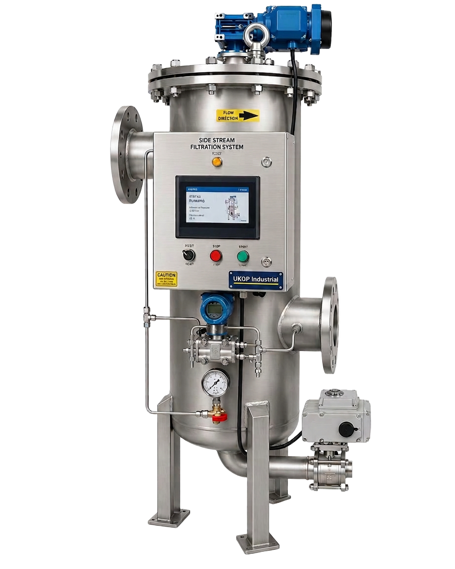
Beyond simple debris removal, a well-placed filtration unit protects expensive downstream components such as plate heat exchangers and control valves from erosion and blockage. When you specify a side stream filtration schematic that includes automated backwash or differential pressure monitoring, you are investing in the long-term reliability of the HVAC system. This clarity in the design phase also facilitates easier procurement and tendering processes, as the scope of works is clearly defined for all parties involved. Whether you are working on a new build or a complex retrofit project, having a clear P&ID ensures that every stakeholder understands the hydraulic requirements, from the plant-room engineer to the procurement lead managing the budget. UKGP skids, starting from £6,800+VAT, provide the robust hardware required to fulfil these design specifications with a standard 2-year warranty.
- Visualise the hydraulic connection points to avoid interference with variable speed drives.
- Ensure compliance with BSRIA BG29 Pre-commissioning cleaning requirements.
- Facilitate easier maintenance by clearly labelling isolation and bypass valves.
- Provide a baseline for commissioning engineers during the handover phase.
P&ID Requirements for Efficient Debris Removal
A technical P&ID must do more than simply show a box labelled 'Filter'; it must detail the bypass arrangement, isolation valves, and local pressure gauges that allow for safe operation. On a standard side stream filtration schematic, the connection is typically made across the main flow and return headers, or across the primary pumps, to leverage the natural differential pressure. However, many modern skids, such as those produced by UKGP, include their own booster pumps to ensure a constant flow rate of 5-15% of the total system volume, regardless of main pump modulation. This distinction must be clearly indicated on your side stream filtration schematic to prevent hydraulic conflicts and to ensure that the filtration rate meets the specific needs of the medium, whether it is heating water or chilled glycol circuits.
For installers, the P&ID serves as a roadmap for the installation of sensors and control interfaces. In a high-specification building, the side stream filtration schematic often includes a link to the Building Management System (BMS) to alert maintenance staff when a bag change or media backwash is required. This level of detail on the drawing ensures that electrical contractors provide the necessary wiring and that the controls engineer understands the logic of the filtration cycle. By including these details early, you reduce the risk of expensive onsite variations and delays. UKGP Industrial offers made-to-order skids that are built to integrate seamlessly with these digital environments, with typical lead times of 6 to 8 weeks for standard DN50 to DN100 connections. This ensures your project stays on schedule without sacrificing technical sophistication.
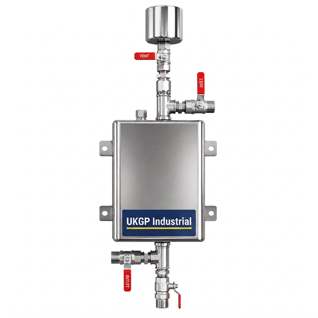
Furthermore, the P&ID should account for the drainage requirements associated with backwashing or filter changes. A common oversight in many plant rooms is the lack of a nearby tundish or drain connection, which can lead to messy maintenance procedures. Your side stream filtration schematic should explicitly show the waste-water path and any necessary backflow prevention devices required by local water regulations. By standardising these details in your drawings, you demonstrate a commitment to best-fit engineering principles that resonate with discerning clients and Facilities Managers. This professional approach to system design, backed by UKGP's engineering expertise, ensures that every component—from the filtration skid to the chemical dosing pot—is perfectly positioned for peak efficiency and ease of use over the system's thirty-year life expectancy.
- Include differential pressure sensors to trigger automated cleaning cycles.
- Specify high-quality isolation valves to allow for filter media replacement without system shutdown.
- Detail the electrical power requirements for the skid's internal booster pump.
- Map the integration with the BMS for remote monitoring and fault logging.
Hydraulic Balancing and the Side Stream Filtration Schematic
Achieving hydraulic balance is a delicate task in modern commercial HVAC systems, and the introduction of a side stream circuit must be handled with care. A precise side stream filtration schematic helps avoid common pitfalls where the filter circuit inadvertently creates a 'short circuit' that starves distant terminal units of flow. By using a dedicated pump on the skid, the side stream system can operate independently of the main system pressure, which is particularly beneficial in systems utilizing variable primary flow. On the side stream filtration schematic, engineers should specify the use of double-regulating valves or fixed orifice plates if they are relying on system pressure alone, though a pumped skid is generally preferred for its consistency and reliability in maintaining BSRIA-compliant water quality levels.
The schematic must also reflect the physical location of the takeoff points; ideally, these should be located on the main return header where the concentration of suspended solids and magnetite is highest before it reaches the heat source. This strategic placement, clearly marked on the side stream filtration schematic, ensures that the most vulnerable components are protected from debris ingress. This is a central tenant of BS 8552, which focuses on the sampling and monitoring of water within buildings. When the schematic matches the physical layout, it becomes easier for site engineers to take accurate water samples and correlate them with the performance of the filtration unit, allowing for data-driven adjustments to the water treatment regime and chemical dosing levels.
UKGP Industrial understands the nuances of hydraulic integration, which is why our skids (DN50 to DN100) are designed with flexibility in mind. We provide the documentation necessary to satisfy CIBSE guidelines on system efficiency and pump power. By choosing a UKGP skid, you are opting for a product that is not only made to order to fit your specific pipework configuration but also backed by a 2-year warranty for peace of mind. Our units are often the preferred choice for M&E contractors who require a high-spec solution that is easy to install and even easier to commission against a formal side stream filtration schematic. Requesting a quote early in the design phase ensures that the long-lead items are accounted for and that the pricing—typically starting from £6,800+VAT—is locked into your project budget.
- Use pumped skids to maintain constant filtration regardless of system demand.
- Place return lines downstream of the takeoff to prevent short-circuiting.
- Reference BS 8552 for sampling points on the schematic to verify filtration efficacy.
- Specify DN50 to DN100 connections based on the total system volume and required turnover.
Protecting Critical Assets: Plate Heat Exchangers
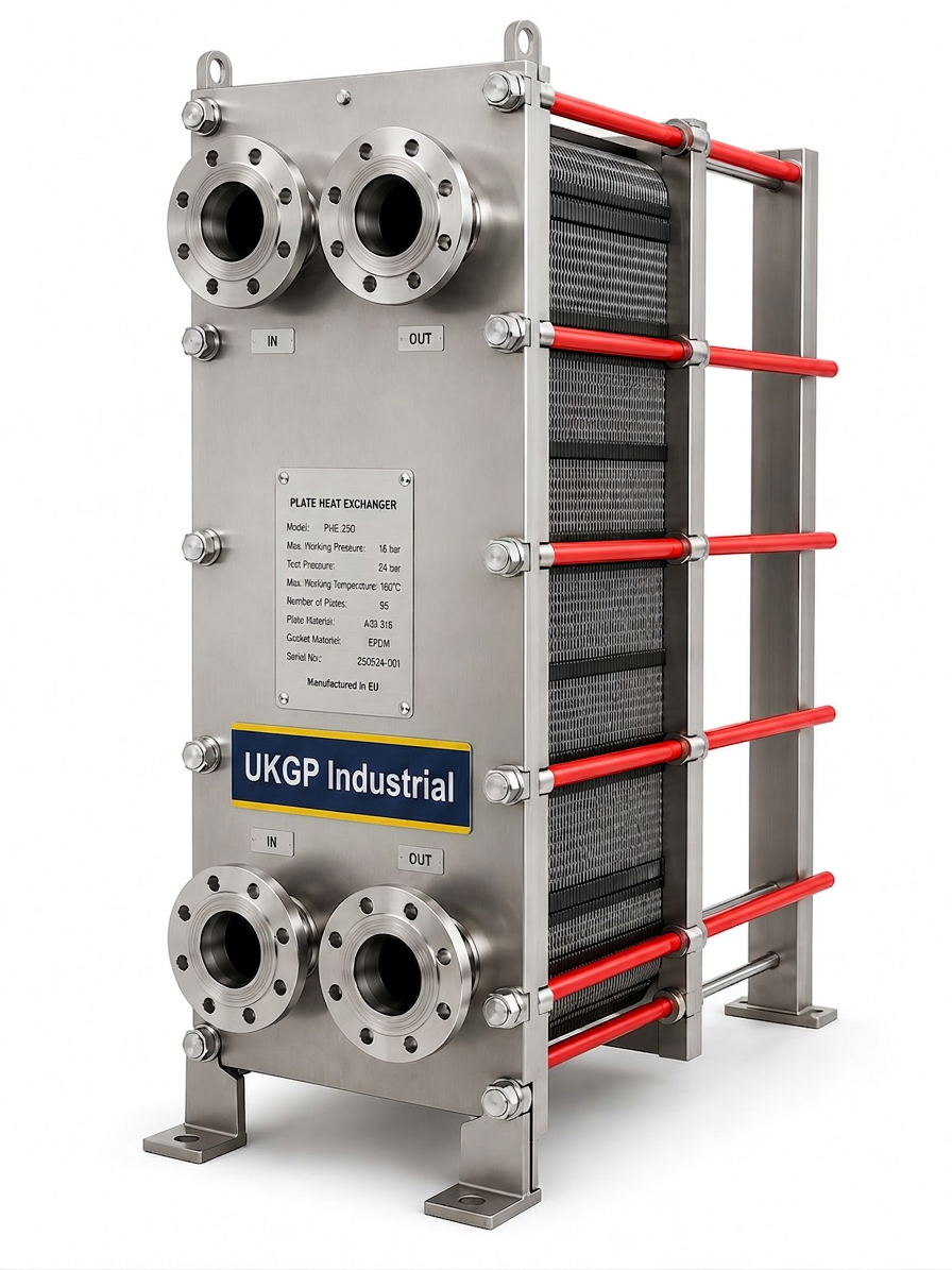
While the primary focus is often on the filtration unit itself, a comprehensive system design must consider the protection of other sensitive components. Integrating a plate heat exchanger into your side stream filtration schematic can be an effective way to separate different pressure zones or to provide heat recovery while maintaining water purity. Plate heat exchangers are notoriously sensitive to fouling from suspended solids; even a thin layer of magnetite can significantly reduce heat transfer efficiency and increase energy costs for the end-user. By placing the filtration skid immediately upstream of the exchange equipment on the P&ID, you create a robust barrier that ensures the tight channels of the plates remain clear of debris, thereby extending the service interval and maintaining thermal performance.
In many commercial applications, the side stream filtration schematic will show the filter following the heat exchanger to catch any scale that might break loose, but the prevailing industry best practice is to prioritise the protection of the exchange surface first. This is where the synergy between different UKGP products becomes apparent. By sourcing both your side stream filtration skid and your plate heat exchanger from a single UK manufacturer, you ensure that the technical specifications, such as flow rates and pressure drops, are perfectly aligned. This holistic approach to plant-room design is favoured by FM leads and procurement professionals who value the simplicity of a single point of contact and a unified warranty structure for their critical HVAC infrastructure assets.
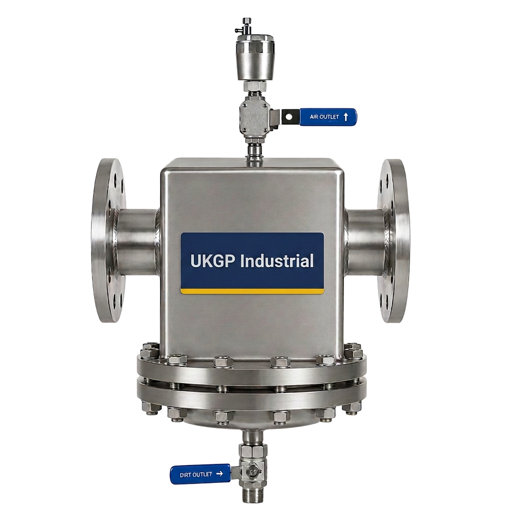
When designing these systems, it is also worth considering the inclusion of air and dirt separators to tackle larger debris and microbubbles before they reach the fine media of the side stream filter. While the side stream filtration schematic focuses on the 5-10 micron range, separators handle the heavier work, reducing the load on the filter bags and extending their life. A well-designed plant room is a tiered defence system, and each component plays a role in satisfying the stringent requirements of BSRIA BG29. Contractors should contact UKGP Industrial to discuss how our range of UK-made products can be integrated into a cohesive package that meets both the technical and budgetary constraints of modern building services projects, with reliable 6-8 week lead times.
- Protect tight plate heat exchanger channels from magnetite-induced fouling.
- Enhance system thermal efficiency by maintaining clean heat transfer surfaces.
- Coordinate flow rates between filtration skids and exchangers for optimal performance.
- Utilise UKGP's technical support to cross-reference component specifications.
Practical Installation and Pre-Commissioning Steps
Once the side stream filtration schematic is finalised and the equipment is on-site, the focus shifts to the practicalities of installation. Installers must pay close attention to the orientation of the skid and the orientation of the connecting pipework. It is essential to ensure that the takeoff and return points are at least 10 pipe diameters apart on the main header to prevent turbulence and ensure a representative flow is diverted into the filter. This detail should be clearly annotated on the side stream filtration schematic to assist the site team. Furthermore, before the system is filled, a thorough inspection of all mechanical joints and electrical connections should be performed, following the manufacturer's guidelines and the project's specific P&ID.
Pre-commissioning cleaning, as outlined in BSRIA BG29, often involves the use of the side stream filter to assist in the removal of temporary flushes and construction debris. During this phase, the side stream filtration schematic becomes the map for the flushing specialist, who will needs to know which valves to open and close to ensure the flushing water passes through the filter media. Because UKGP skids are made to order, we can include specific features like high-capacity bag housings for the initial cleanup phase, which can then be swapped for finer cartridges for long-term operation. This versatility makes our equipment a favourite for contractors who are responsible for the system from construction through to the 2-year warranty period and beyond.
Finally, the commissioning process must include a verification of the flow rates shown on the side stream filtration schematic. Using a calibrated flow meter, the engineer should confirm that the side stream loop is pulling the correct percentage of the total system volume. This is a critical step in achieving BSRIA BG50 compliance, as it proves that the filtration rate is sufficient to maintain low turbidity levels. Documentation is key here; the final 'as-built' schematic should be updated with the actual flow rates and pressure settings observed during commissioning. For projects requiring reliable, Surrey-manufactured equipment, UKGP Industrial stands ready to provide the high-performance skids (DN50-DN100) and technical expertise needed to ensure your next installation is a success from day one.
- Verify 10-pipe-diameter spacing for takeoff and return on the main header.
- Use high-capacity filter bags during the BG29 flushing and cleaning phase.
- Document commissioned flow rates on the final as-built schematic.
- Ensure all technicians are briefed on the specific valve operations of the UKGP skid.
Maintenance Protocols Based on the P&ID
Long-term system health is dependent on a structured maintenance regime that is informed by the original side stream filtration schematic. Facilities Managers should use the P&ID to create a maintenance checklist, ensuring that bypass valves are functional and that sensors are calibrated annually. The schematic identifies the critical path for water flow, allowing the FM team to isolate the filter for cleaning without interrupting the heating or cooling supply to the building. Without a clear side stream filtration schematic, there is an increased risk that the filter will be left in bypass indefinitely, leading to a rapid accumulation of sludge and a subsequent decline in system efficiency, which ultimately increases operational costs and the risk of component failure.
We recommend that water samples are taken regularly from the points identified on the schematic to verify that the filtration skid is performing as expected. If the iron levels or turbidity begin to rise, the side stream filtration schematic can help troubleshoot whether the issue is a hydraulic bypass or a spent filter media. Our UKGP Industrial skids are designed for ease of maintenance, with clear indicators for cartridge replacement. Starting from £6,800+VAT, these units represent a cost-effective insurance policy against the thousands of pounds in repairs that can result from poor water quality. By following the P&ID and the manufacturer’s instructions, you ensure the 2-year warranty remains valid and the building’s HVAC system remains ‘fit for purpose’ for decades.
Ultimately, the side stream filtration schematic is more than just a drawing; it is a vital piece of technical documentation that supports the entire lifecycle of the building. From the initial procurement of a made-to-order DN50-DN100 skid with a 6-8 week lead time to the daily monitoring by the on-site engineer, the schematic ensures consistency and quality. At UKGP Industrial, we are committed to supporting UK building services professionals with the hardware and the technical knowledge necessary to implement world-class water treatment solutions. Contact us today to request a quote or to discuss your specific schematic requirements with our Surrey-based engineering team, and let us help you deliver a project that exceeds industry standards for efficiency and reliability.
- Create an FM maintenance schedule based on the P&ID isolation points.
- Conduct regular water quality testing at the sampling points identified in the design.
- Monitor pressure drops across the filter as indicated on the schematic.
- Schedule annual calibrations for all linked BMS sensors and skid controllers.
Frequently asked questions
Where should the side stream filter be located on my schematic?
- It should typically be installed on the main return header, across the pumps or with its own booster pump, to capture debris before it reaches the boiler or chiller. This ensures maximum protection for heat exchange surfaces.
What flow rate should be shown on the side stream filtration schematic?
- BSRIA guidelines generally recommend a filtration rate of 5% to 15% of the total system volume per hour. Your schematic should specify the pump duty required to achieve this turnover.
Why is a side stream filtration schematic necessary for BSRIA BG29 compliance?
- BG29 requires a clear plan for pre-commissioning cleaning. The schematic proves that the system has a dedicated method for removing the suspended solids generated during the cleaning and flushing process.
Does the P&ID need to include a booster pump for the filter?
- While not always mandatory, including a booster pump on your side stream filtration schematic ensures a constant flow rate. UKGP skids often include these to guarantee performance regardless of the main system's varying pressure.
What are the lead times for a UKGP side stream filtration skid?
- Our skids are made to order in our UK facility with a typical lead time of 6-8 weeks. They range from DN50 to DN100 and come with a 2-year warranty as standard.