Core Components of the Plate and Frame Heat Exchanger Diagram
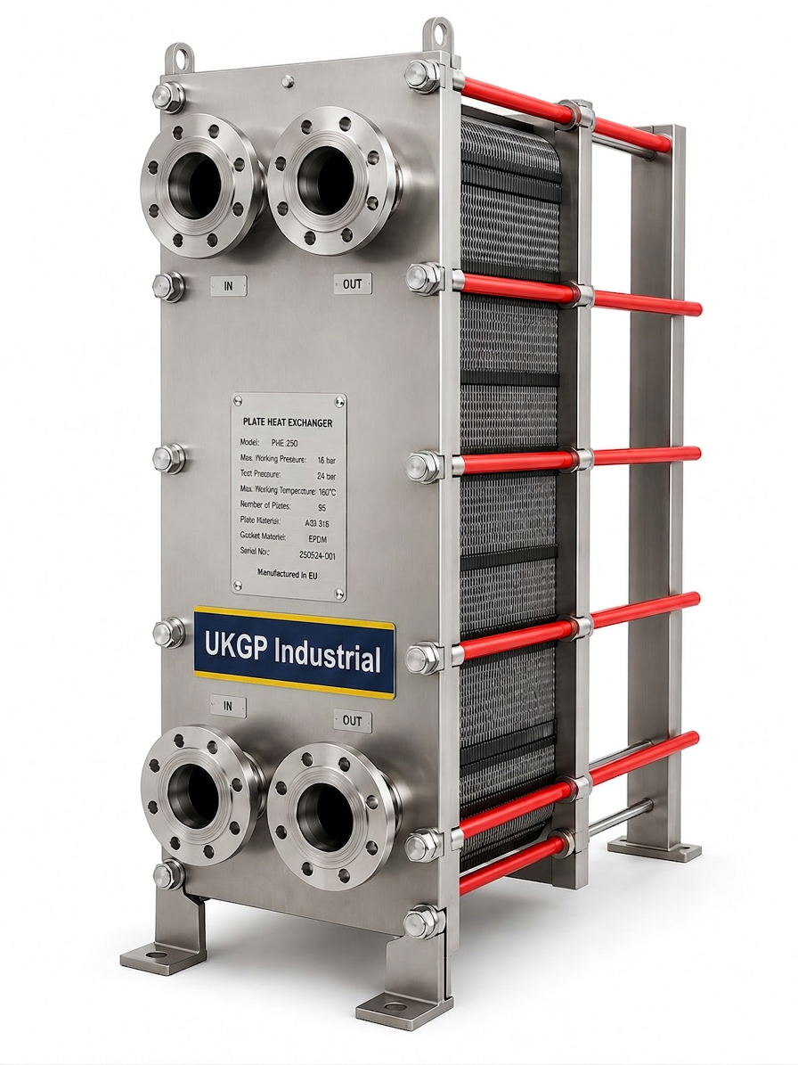
In any professional mechanical specification, the plate and frame heat exchanger diagram serves as the blueprint for understanding how thermal energy moves between the primary and secondary circuits without cross-contamination. At its most fundamental level, the assembly consists of a series of corrugated metal plates that are held securely between a fixed frame plate and a movable pressure plate. This structure is supported by a top carrying bar and a bottom guide bar, ensuring that the plates remain perfectly aligned even when subjected to significant hydraulic forces during system start-up. In the UK market, these units must be sized accurately to meet the specific peak loads of a building, often requiring a detailed thermal profile to determine the exact number of plates required.
The tightening bolts, often referred to as tie-rods, are critical elements shown on a plate and frame heat exchanger diagram as they provide the compressive force necessary to seal the unit. Unlike brazed variants, gasketed plate heat exchangers allow for mechanical disassembly, which is vital for maintenance cycles governed by BSRIA BG50 guidelines. Engineers must pay close attention to the 'A-dimension'—the distance between the inner surfaces of the frame and pressure plates—to ensure that the gaskets are compressed to the manufacturer's precise specification. Incorrect tightening can lead to external leaks or, in catastrophic cases, internal bypass, which compromises the efficiency of the entire DHW or LTHW system and increases operational costs for facility managers.
Precision in the design stage is paramount for long-term reliability in UK plant rooms. UKGP offers a comprehensive range of Gasketed and Brazed Plate Heat Exchangers, spanning DN20 to DN300 connections to suit various commercial scales. When you provide us with a full thermal spec, we can offer sizing expertise to ensure the unit fits the hydraulic requirements of your project perfectly. Backed by a 2-year warranty and a standard lead time of 4-6 weeks, our units are engineered to withstand the rigours of modern heating and cooling demands, providing a robust solution for contractors who require both quality and short project lead times.
- Fixed Frame Plate: The heavy-duty stationary end of the unit containing the connection ports.
- Movable Pressure Plate: The adjustable rear plate used to compress the plate pack.
- Carrying Bar: The top horizontal rail that supports the weight of the plates.
- Tie Rods: High-tensile bolts used to maintain the design compression limit.
The Role of Gaskets and Flow Channels in Thermal Transfer
When examining a plate and frame heat exchanger diagram, one will notice the intricate pattern of the gaskets that direct the fluid flow between adjacent plates. These gaskets create a complex series of parallel channels where the hot and cold media flow in opposite directions, a process known as counter-current flow. This configuration is highly efficient as it maintains a consistent temperature gradient across the heat transfer surface, allowing for very close temperature approaches. In UK commercial applications where energy efficiency is dictated by CIBSE guidelines, achieving a 1-degree or 2-degree approach can significantly reduce the energy consumption of primary heat sources like heat pumps or high-efficiency boilers.
The corrugated pattern on the plates, often shown in a cross-sectional plate and frame heat exchanger diagram, serves two main purposes: increasing the available surface area for heat transfer and inducing turbulence in the fluid. Turbulence is essential because it disrupts the boundary layer of the fluid, which increases the heat transfer coefficient while also providing a self-cleaning effect that helps to reduce fouling. However, high turbulence also results in a greater pressure drop across the unit. Balancing these factors requires sophisticated software and a high level of engineering expertise to ensure that the chosen heat exchanger does not place an undue burden on the system pumps, leading to excessive electrical consumption.
In accordance with BS 8552, the water quality within these channels must be carefully monitored to prevent the accumulation of scale and corrosion. If the internal channels become restricted, the heat transfer efficiency drops rapidly, and the pressure drop increases, often leading to system failure or poor comfort levels for building occupants. UKGP's expertise in heat transfer ensures that our plate packs are designed with the optimal chevron angle for your specific application, balancing thermal performance with hydraulic requirements. Whether you require a DN50 unit for a localized heat interface or a DN300 unit for an industrial process, our engineers are ready to assist with full technical support and sizing.
- Counter-current flow: Maximising the log mean temperature difference for better efficiency.
- Chevron patterns: Inducing turbulence to increase heat transfer and reduce fouling rates.
- Elastomer gaskets: Available in NBR, EPDM, or Viton depending on the fluid temperature and chemistry.
- Pressure drop management: Ensuring the unit remains within the pump's operational envelope.
Integrating Air and Dirt Separation for Plate Protection
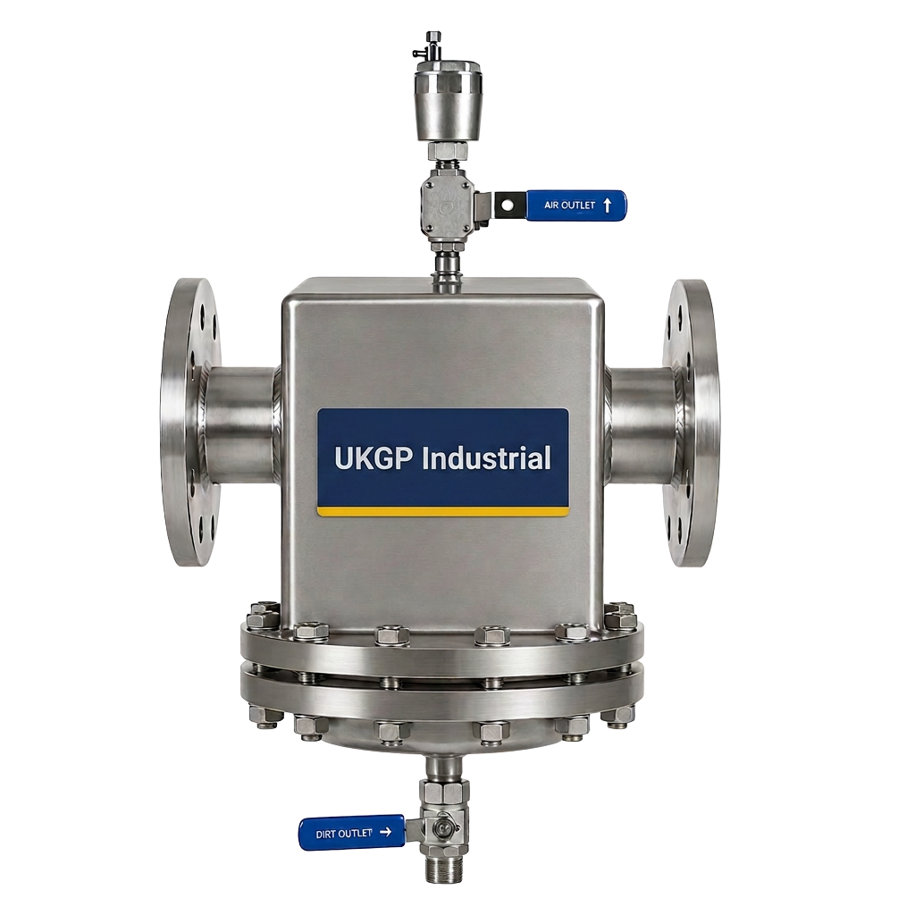
Protecting the delicate internal channels shown on a plate and frame heat exchanger diagram is essential for system longevity. Debris such as magnetite, welding slag, and installation grit can easily become trapped within the plate pack, leading to localized hotspots and accelerated corrosion. This is why BSRIA BG29 and BG50 strongly recommend the installation of high-quality separation equipment on the primary and secondary return lines. By removing both micro-bubbles and solid particles from the circulating fluid, you can ensure that the heat exchanger surfaces remain clean and that the thermal performance specified at the design stage is maintained throughout the life of the building.
The use of an air and dirt separator is particularly important when commissioning new systems or when retrofitting modern plate heat exchangers into older pipework networks. Older systems often contain significant amounts of suspended solids that will quickly clog the narrow gaps between the plates. Incorporating these protective measures reduces the frequency of manual cleaning and gasket replacement, thereby lowering the total cost of ownership for the facility manager. When contractors follow a plate and frame heat exchanger diagram during installation, they should always look for the upstream placement of these separators to provide the most effective protection for the heat transfer surfaces.
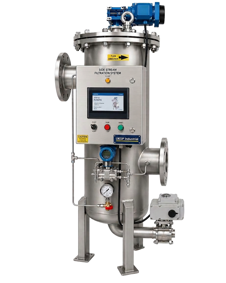
UKGP provides a full suite of plant room components designed to work in harmony with our plate heat exchangers. High-performance air and dirt separators, along with side-stream filtration units, are essential for maintaining the water quality standards required by modern warranties. By specifying a complete solution from UKGP, you gain the peace ofman assurance that all components are sized and selected to provide maximum protection for your investment. This holistic approach to plant room design is what sets leading M&E contractors apart, ensuring that the systems they install are reliable, efficient, and easy to maintain over their multi-decadal life cycles.
- Deaeration: Removing micro-bubbles to prevent oxidative corrosion and pump cavitation.
- Magnetic separation: Capturing magnetite that would otherwise coat the heat exchanger plates.
- Maintenance cycles: Extending the time between plate pack cleaning through better water quality.
- Efficiency gains: Maintaining low pressure drops by preventing internal debris buildup.
Sizing and Specification Requirements for UK Projects
When a consultant requests a plate and frame heat exchanger diagram for a new project, the starting point is always the thermal specification. This includes the flow rates, inlet and outlet temperatures for both the primary and secondary sides, and the allowable pressure drop. In the UK, CIBSE CP1 and other heat network standards have placed a renewed focus on keeping return temperatures low to maximise the efficiency of heat pumps and district heating connections. A correctly sized plate heat exchanger is the 'thermal bridge' that makes these goals achievable. If a unit is undersized, it will fail to meet the peak demand; if it is oversized, it may lead to control hunting and inefficient operation at part-load.
The lead time for bespoke gasketed heat exchangers is a critical factor in project management. At UKGP, we understand that site schedules are often tight and delays can be costly. By maintaining a robust supply chain and local engineering expertise, we offer a consistent 4-6 week lead time for our gasketed units. This allows contractors to plan their installation phases with confidence, knowing that the equipment will arrive on-site precisely when needed. Each unit is built to order, ensuring that the metallurgy of the plates and the material of the gaskets are perfectly matched to the specific fluids and temperatures of your unique application, whether it is standard LTHW or more corrosive industrial processes.
Furthermore, our commitment to quality is backed by a 2-year warranty on all gasketed and brazed units. This warranty provides piece of mind for consultants and procurement leads who need to prove the value and reliability of the equipment they specify. By choosing a UKGP plate heat exchanger, you are not just buying a piece of hardware; you are gaining access to a technical partnership. We provide the detailed drawings and data sheets required for your BIM models, ensuring that the integration of the heat exchanger into your wider system design is seamless and fully documented according to the latest UK building regulations and standards.
- Connection sizes: DN20 to DN300 to accommodate flow rates from local to district scales.
- Plate materials: 304/316 Stainless Steel or Titanium for specialized cooling applications.
- Gasket materials: Standard EPDM for heating; NBR for oils and specific chemical processes.
- Thermal accuracy: Units sized precisely from full thermal specs to meet CIBSE efficiency targets.
Maintenance Protocols and BSRIA Compliance
Ongoing maintenance of the components highlighted in a plate and frame heat exchanger diagram is non-negotiable for system health. Over time, even with good water treatment, gaskets can lose their elasticity and plates can accumulate a thin film of scale. BSRIA BG50 provides a framework for water treatment and maintenance in closed-circuit systems, emphasizing the need for regular inspection and cleaning. Gasketed units have a significant advantage here over brazed units, as they can be stripped down, cleaned, and re-gasketed without the need to replace the entire assembly. This 'circular' approach to equipment maintenance is increasingly favoured in UK sustainability assessments and lifecycle cost analyses.
When performing an 'overhaul' as indicated by the frequency of service, engineers must check for plate deformation and signs of pitting corrosion. It is also the ideal time to inspect the frame for any structural integrity issues or corrosion on the tie-rods. Re-assembling the unit requires a careful following of the plate and frame heat exchanger diagram to ensure the plates are reinstalled in the correct order (usually an A-B-A-B sequence). Failure to follow the manufacturer's sequence will result in internal bypass and a total loss of thermal performance. Once reassembled, the unit must be pressure tested to ensure that the gaskets have seated correctly and that the 'A-dimension' is within the specified tolerance.
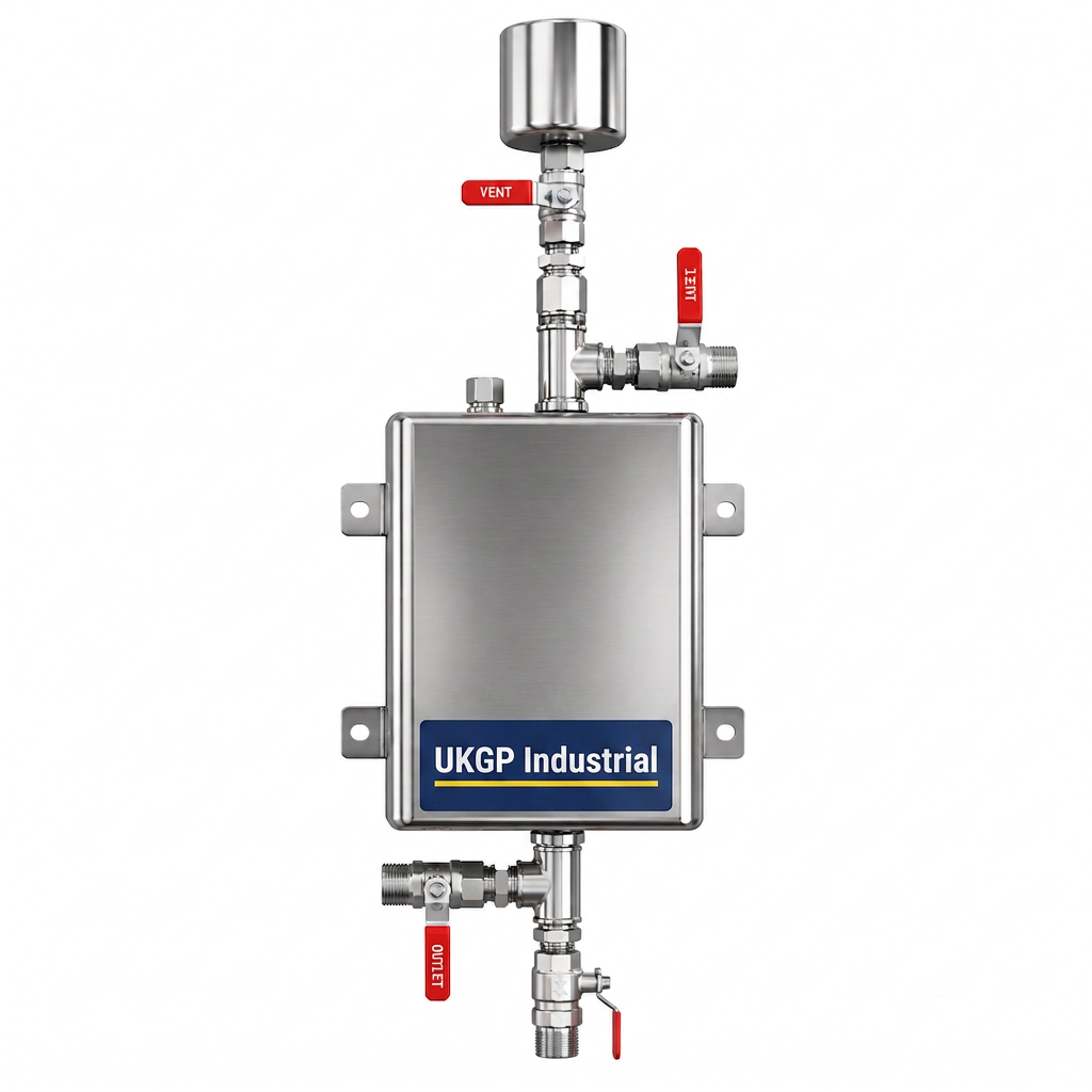
For plant room engineers, having a stocked supply of spare gaskets and a clear understanding of the plate sequence is essential for minimizing downtime. UKGP supports our clients by providing clear documentation and technical advice for all maintenance activities. We advocate for a proactive approach, including the use of dosing pots and side-stream filtration to keep the system water clean, which directly extends the interval between heat exchanger services. By investing in high-quality equipment and following a rigorous maintenance schedule, building owners can protect their assets and ensure that their heating and cooling systems operate at peak efficiency for many years to maintain comfort and compliance.
- A-Dimension check: Crucial during re-assembly to prevent gasket failure and leaks.
- Plate sequencing: Ensuring the 'honeycomb' structure is maintained for correct fluid paths.
- Pressure testing: Verifying integrity before re-introducing high-temperature or high-pressure fluids.
- Gasket replacement: Planning for cycle-end renewals to prevent emergency shutdowns.
Strategic Integration and Procurement of Heat Exchangers
Selecting the right partner for heat transfer solutions involves more than just looking at a plate and frame heat exchanger diagram; it requires a partner who understands the nuances of UK engineering standards. Procurement leads must weigh the initial capital cost against the long-term operational efficiency and the reliability of the supplier. UKGP stands out in the Surrey and wider UK market by offering technical excellence combined with commercial agility. Our ability to size units from DN20 to DN300 means we can serve as a single-source supplier for an entire project, from small-scale domestic water heating to large-scale industrial cooling towers.
Our 2-year warranty is a testament to the confidence we have in our manufacturing processes and the durability of our materials. When you integrate a UKGP unit into your plant room, whether it is a gasketed plate heat exchanger or a brazed model for high-pressure CO2 applications, you are choosing a product designed for the long haul. We encourage all M&E contractors and consultants to reach out early in the design stage. By providing us with your full thermal specification, we can provide not only a quote but also the technical drawings and performance data required to de-risk your project and ensure that the final installation meets all performance benchmarks set by the client.
In conclusion, the plate and frame heat exchanger diagram is an indispensable tool for anyone involved in the design, installation, or maintenance of UK building services. Understanding its parts—from the frame plates and tie-rods to the complex arrangement of gaskets and plates—is the key to unlocking system performance. UKGP is dedicated to supporting the UK industrial and commercial sectors with high-quality heat exchangers, short 4-6 week lead times, and the expert knowledge needed to navigate the complexities of modern thermal engineering. Contact us today to discuss your next project and see how our plate heat exchanger solutions can drive efficiency in your plant room.
- Technical Partnership: Professional sizing and selection based on UK building requirements.
- Single-Source Supply: From low loss headers to plate heat exchangers and dosing pots.
- Reliability: 2-year warranty as standard on all gasketed and brazed PHE units.
- Rapid Response: 4-6 week lead times to keep your construction programme on track.
Frequently asked questions
What is the primary benefit of using a gasketed plate heat exchanger?
- The main benefit is maintainability. Unlike brazed units, gasketed plate heat exchangers can be opened for cleaning, inspection, or the addition of plates to increase capacity, which is essential for compliance with BSRIA BG50.
How do I choose between a gasketed and a brazed heat exchanger?
- Gasketed units are preferred for large duties or where frequent cleaning is required. Brazed units are more compact and suited for high-pressure applications or smaller duties where maintenance access is not a primary concern.
Why is the A-dimension important on a plate and frame heat exchanger diagram?
- The A-dimension is the manufacturer-specified distance the plate pack must be compressed to. If it is too large, the gaskets won't seal; if it is too small, the plates may be permanently deformed.
What information do I need to provide for a sizing quote?
- To provide an accurate thermal spec sizing, we require the fluid types, inlet/outlet temperatures for both sides, the heat load (kW), and the maximum allowable pressure drop.
Does UKGP provide technical drawings for my project?
- Yes, we provide detailed technical drawings and data sheets for all our plate heat exchangers to assist consultants and contractors with BIM modeling and system integration.