Regulatory Framework and Valve Selection
The selection of a gas solenoid valve is governed by BS EN 161:2011+A3:2013, which categorises valves based on their performance and safety characteristics. For UK building services, Class A valves are standard, requiring a closing time of less than one second. Engineers must ensure the valve is compatible with the gas family in use—Natural Gas (Methane), LPG (Propane/Butane), or Town Gas. Installation must also adhere to IGEM/UP/2 (Edition 3) for industrial and commercial gas installations.
When determining the correct size, engineers should not simply match the existing pipework diameter. A pressure drop calculation is essential; an undersized valve will lead to starvation at the burner and potential 'nuisance' lockouts during high-demand periods. Conversely, an oversized valve can lead to poor control if modulating, although for shut-off duties, matching the pipe size is generally acceptable provided the flow capacity exceeds the cumulative load of the plant room at peak firing.
Building services designers must also consider the environment. If the valve is located in an area with high moisture or potential for hosing down, an IP65-rated coil or protective housing is required. For most internal plant rooms, IP54 is the baseline standard, but engineers should always lean toward higher protection if the environment is unheated or damp.
- Presence of Flame Supervision Devices (FSDs) on all downstream appliances.
- Total heat input (kW) and required flow rate (m³/h).
- Inlet pressure vs. pressure drop across the valve (typically <1 mbar for low-pressure systems).
- Pipe size and connection type (Threaded BS EN 10226-1 or Flanged PN16).
Pre-Installation Requirements and Mechanical Alignment
Before a gas solenoid valve is introduced to the system, the upstream pipework must be thoroughly purged and cleaned. Debris such as swarf, thread tape, or scale is the leading cause of valve failure, preventing the disc from seating correctly and leading to 'let-by.' BSRIA BG29/21 guidelines for pre-commissioning cleaning provide a useful framework here, although for gas lines, the focus is on pneumatic purging and the removal of solid particulate.
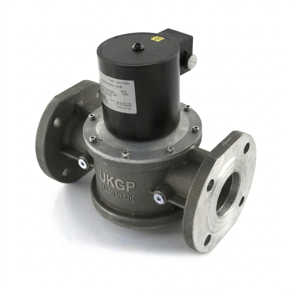
The physical orientation of the valve is critical. Most UKGP Industrial gas solenoid valves are designed for horizontal mounting with the actuator/coil in the upright position. While some models allow for a 90-degree tilt, mounting a valve upside down is strictly prohibited as it allows condensate and debris to accumulate in the solenoid tube, leading to premature coil burnout or mechanical seizing. Technical data sheets should always be consulted for the specific angular tolerances allowed.
Alignment of the pipework is equally vital. Applying excessive torque to the valve body to 'pull' misaligned pipes together can warp the valve seat or crack the casing. For threaded connections, use a high-quality thread sealant approved for gas (e.g., BS 6956 Part 5). For flanged PN16 connections, ensure even cross-bolting to the correct torque settings to prevent stress on the valve flanges.
- Cleaning and purging the upstream pipework to BS EN 12327.
- Verifying the direction of flow (marked by an arrow on the valve body).
- Ensuring the solenoid coil is not used as a lever during installation.
- Maintaining minimum clearances for coil replacement and manual reset operations.
Electrical Wiring and Integration with Safety Systems
The electrical installation must comply with BS 7671 (IET Wiring Regulations). Gas solenoid valves are typically 230V AC or 24V DC. Because these are automatic-reset valves, they remain open as long as they are energised. This makes them the ideal component for interlocking with broader safety systems. In the event of a fire alarm activation, the power supply to the valve is cut, causing it to fail-safe into the closed position instantly.
Modern plant room design often requires the solenoid to be interlocked with the ventilation system. If the extract fans are not proving sufficient airflow (monitored via air pressure differential switches), the gas supply must be isolated to prevent the accumulation of combustion by-products. This is a mandatory requirement in commercial kitchens under BS 6173 and is increasingly becoming best practice in industrial boiler houses.
When wiring to a Building Management System (BMS), engineers should consider using a valve with an integral closed-position indicator (CPI) switch. This provides a volt-free contact back to the BMS to confirm the valve is physically closed, rather than just de-energised. This feedback loop is essential for high-integrity safety systems and helps FM teams diagnose 'no gas' faults quickly without entering the plant room.
- BMS integration for remote shut-off and status monitoring.
- Interlocking with Carbon Dioxide (CO2) or Natural Gas leak detection systems.
- Connection to the Emergency Stop (E-Stop) circuit.
- Integration with the Fire Alarm Control Panel (FACP).
Commissioning and Strength Testing
Once installed, the valve must be commissioned by a Gas Safe registered engineer with the appropriate commercial (COCN1) or industrial competencies. The first step is a tightness test in accordance with IGEM/UP/1 or UP/1A. This ensures that when the solenoid is de-energised, the seat tightness meets the requirements of BS EN 161 (Class A). No let-by should be detectable using a standard U-gauge or electronic manometer over the prescribed test duration.
The strength test should be conducted with the valve in the open position to ensure the integrity of the body and the seals around the solenoid tube. Engineers must be careful not to exceed the maximum operating pressure (MOP) of the valve during testing. Many solenoid valves have a maximum inlet pressure of 200 mbar or 500 mbar; applying a high-pressure pneumatic test (e.g., 2 bar) without isolating the valve can rupture the internal diaphragm or damage the seat.
Functional testing must include cycling the valve several times under line pressure. The engineer should listen for a distinct 'click' on energisation and verify that the gas flow begins. More importantly, the 'trip' mechanism must be tested. Actuating a remote E-stop or simulating a gas leak should result in the immediate closure of the valve. The response time should be sub-one-second to meet UK safety standards.
- Visual inspection for physical damage or corrosion.
- Tightness testing (Let-by test) to ensure zero leakage.
- Electrical continuity and insulation resistance testing.
- Operational sequencing: Testing the E-Stop and BMS trip functions.
Troubleshooting Common Operational Issues
A frequent issue in older plant rooms is 'solenoid hum.' This is often caused by dust or debris entering the armature tube, preventing the magnetic core from seating fully. This creates an air gap in the magnetic circuit, causing the coil to vibrate at 50Hz. If left unaddressed, this vibration will cause the coil to overheat and eventually fail. Cleaning the internal plunger and checking the AC supply voltage can often resolve this.
If a valve fails to open despite being energised, the voltage at the coil terminals should be checked. If the voltage is significantly lower than the rated 230V or 24V, the valve may lack the 'pull-in' force required to lift the disc against the gas pressure and spring tension. This is common in long cable runs where the wire gauge is insufficient. Conversely, if the coil is hot and there is no continuity, the internal windings have likely burnt out, necessitating a coil replacement.
Intermittent closing (nuisance tripping) is often traced back to the safety interlock circuit rather than the valve itself. Loose connections in the fire alarm interface, or 'hunting' air pressure switches in the ventilation ductwork, can momentarily break the circuit. In these cases, installing a small time-delay relay in the interlock circuit (where permitted by local regulations) or tightening all control circuit terminals is the prescribed fix.
- Voltage drops causing the valve to 'chatter' or fail to open.
- Coil burnout due to continuous duty in poorly ventilated areas.
- Noise/Humming caused by AC hum or debris in the magnetic circuit.
- Partial opening due to low supply pressure or mechanical obstruction.
Maintenance Protocols and Lifecycle Management
Gas solenoid valves are generally low-maintenance units, but they are not 'fit and forget.' IGEM/UP/2 recommends annual inspections of all gas-carrying components. The most critical maintenance task is the verification of the upstream strainer. Most industrial installations should feature a gas filter (typically 50 microns) placed immediately before the solenoid valve to protect the precision-machined seat from pipeline scale.
The lifespan of a solenoid coil is influenced by the ambient temperature. In plant rooms where temperatures exceed 40°C, the insulation in the coil can degrade over time. FM managers should keep a record of the age of these components; a proactive replacement of the coil every 5-7 years is often more cost-effective than an emergency call-out following a terminal failure. UKGP Industrial valves are designed for easy coil replacement without needing to break the gas line.
Documentation is a key part of the maintenance cycle. Every test of the gas safety shut-off system should be logged in the site's Gas Safety Record. This should include the date, the name of the engineer, the results of the tightness test, and confirmation that all interlocks (fire, CO2, ventilation) successfully tripped the valve. This audit trail is essential for insurance compliance and RIDDOR-related safety investigations.
- Annual let-by testing as part of the gas safety inspection.
- Visual checking of the coil for signs of heat stress or cracking.
- Testing the manual override (if fitted) to ensure it is not seized.
- Cleaning of upstream strainers to prevent particulate ingress.
Advanced Configurations: Slow-Opening and Gas Proving
In systems with high flow rates or long downstream pipe runs, a 'fast-opening' valve can cause a pressure surge known as gas hammer. This can damage sensitive burner components or trip low-pressure switches. In these scenarios, a slow-opening solenoid valve is preferred. These valves feature a hydraulic damper that allows the disc to rise slowly over 5 to 30 seconds, providing a smooth ramp-up in gas pressure.
Gas proving systems are a distinct step up from standard solenoid installations. Used primarily in laboratories and commercial kitchens, a gas proving system (such as those compliant with IGEM/UP/11) includes a controller that performs a small-scale pressure test on the downstream pipework before allowing the main solenoid valve to open. This ensures that no gas taps have been left open and that the system is gas-tight before the main supply is restored.
Engineers must also distinguish between automatic-reset and manual-reset valves. An automatic-reset valve will reopen as soon as power is restored (provided the interlock is healthy). A manual-reset valve, however, requires a human operator to physically pull a lever or press a button to restore gas flow. Manual-reset valves are often specified in high-risk industrial environments or where a process must be supervised during startup after a safety shutdown.
- Direct-acting: Best for low-pressure, zero-differential applications.
- Servo-operated: Require a minimum pressure differential to function.
- Slow-opening: Used to prevent 'gas hammer' and burner shocks.
- Manual-reset: Requires a technician to manually latch the valve open.
The Future of Gas Safety Control
The transition toward hydrogen-blended gas in the UK grid is beginning to influence valve specifications. While standard natural gas solenoid valves are compatible with low percentages of hydrogen, higher blends may require different seal materials to prevent embrittlement. Engineers currently specifying equipment for 25-year lifespans should consult with manufacturers like UKGP Industrial regarding the future-proofing of their valve selections.
Digital integration is the other major shift. Newer solenoid valve actuators are being developed with built-in diagnostics that can report their own 'operating temperature' and 'cycles performed' back to a cloud-based FM portal. This move toward predictive maintenance allows engineers to replace a failing solenoid before it shuts down a critical process or heating load for a hospital or school.
Despite these technological advances, the fundamental principles of gas safety remain the same. The solenoid valve remains the "sentinel" of the plant room. By following the rigorous installation and commissioning standards outlined in this guide, UK building services engineers can ensure they meet their legal obligations while providing a safe, reliable environment for the end-user. Responsibility for gas safety is absolute, and the solenoid valve is the single most important tool in achieving it.
- Mandatory use of Class A valves in safety-critical lines.
- Standardisation of IP ratings for plant room environments.
- Emphasis on BS EN 161 compliance for all imported components.
- Integration of 'smart' monitoring for predictive maintenance.
Frequently asked questions
Can I use a standard solenoid valve for gas proving?
- No. Under BS 6173 and IGEM/UP/19, if an appliance does not have flame supervision devices (FSDs), a gas proving system is required. However, for most modern plant rooms with FSDs, a standard automatic-reset solenoid is appropriate, provided it is interlocked with the fire alarm or BMS.
What is the difference between Class A and Class B valves?
- UK commercial gas installations typically require Class A or Class B valves. Class A valves, which must close in less than one second and maintain a high level of seat tightness, are the standard for main safety shut-off duties.
Why are gas safety valves always Normally Closed (NC)?
- The 'NC' designation means the valve remains closed when de-energised. Power is required to open the valve and keep it open. In the event of a power failure or a BMS signal trip, the valve fails to the safe (closed) position.
Can these valves be used for LPG installations?
- Yes, provided the LPG-specific torque and seal compatibility (usually Viton or NBR) are confirmed by the manufacturer. The installation must also comply with UKLPG Code of Practice 22.
Is vertical installation permitted?
- Vertical installation (upward flow) is generally permitted, but the actuator must never be mounted upside down (below the pipe). Horizontal installation is always preferred to minimise debris accumulation on the seal.


