Identifying Coil Failure in Gas Trains
Before commencing replacement, it is essential to distinguish between a mechanical valve failure and an electrical coil failure. A solenoid coil functions by creating an electromagnetic field that lifts the plunger against a spring-loaded seat. In industrial gas applications, these coils are subjected to high thermal loads due to being energised for long periods. Failure often manifests during a power cycle or after a BMS-initiated shut-off.
If the valve does not open when the control system indicates a 'gas on' status, technicians should first verify the supply voltage at the DIN plug terminals. If 230V AC (or the rated voltage) is present but the valve fails to 'click' or open, the coil winding has likely failed. A resistance check (Ohm test) across the coil terminals is the definitive diagnostic; a healthy coil will show a specific resistance value, whereas a failed coil will show an open circuit or zero resistance in the event of a short.
- Failure to energise (valve remains closed despite 230V signal).
- Audit of the coil body for discolouration, bubbling, or a 'burnt' aroma.
- Continuity testing using a multimeter (infinite resistance indicates an open circuit).
- Internal short circuits causing the local fuse or MCB to trip.
Pre-Replacement Safety and Preparation
Safety in commercial plant rooms is governed by the Electricity at Work Regulations 1989 and the Gas Safety (Installation and Use) Regulations 1998. Before attempting a coil replacement, the electrical circuit must be safely isolated and locked off. It is a common error to assume a 'BMS signal off' constitutes safe isolation; always use a physical lock-out tag-out (LOTO) procedure on the local isolator.
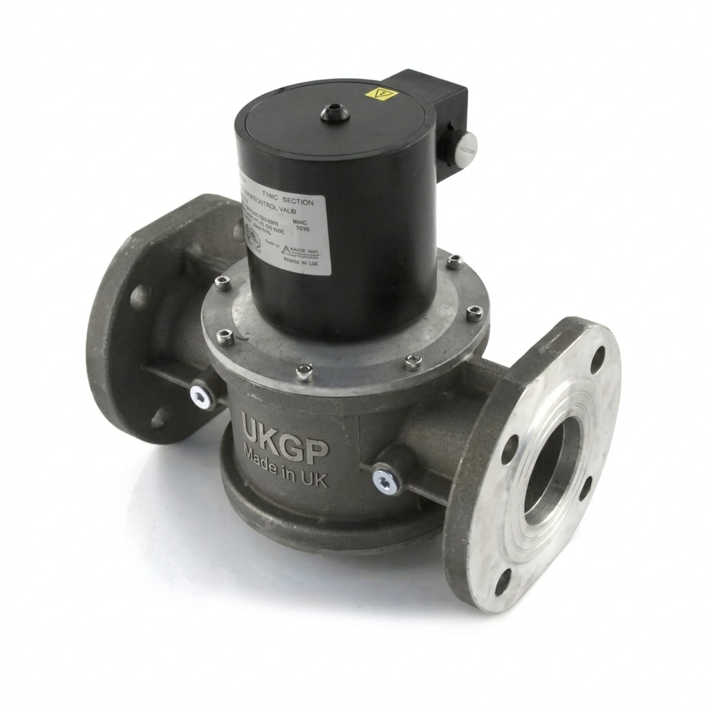
Furthermore, ensure that the replacement coil is an exact match for the valve body. Gas solenoid valves, such as those from the UKGP Industrial range, are precision-engineered. Using an under-powered or incorrectly rated coil could result in the valve failing to lift against the inlet pressure (measured in mbar), particularly in high-pressure installations where the differential pressure is significant.
- Isolate the electrical supply at the local rotary isolator.
- Verify the absence of voltage using a calibrated 2-pole tester.
- Consult the valve data plate to confirm the replacement coil matches the original specification.
- Ensure the gas supply is isolated via the manual quarter-turn valve upstream of the solenoid.
Frequently asked questions
Can I swap a 230V coil for a 24V coil if the valve body is the same?
- No. Solenoid coils work via inductance and are designed for specific voltages (typically 230V AC or 24V DC). Replacing a coil with an incorrect voltage rating will either lead to immediate failure or prevent the valve from opening. Always match the coil specifications to the technical data plate on the valve body.
Why do gas solenoid coils fail prematurely in commercial plant rooms?
- Solenoid coils are typically rated for 100% continuous duty. However, excessive heat is the primary cause of failure. Ambient temperatures exceeding 60°C, poor ventilation in plant rooms, or voltage fluctuations that cause the coil to run 'hotter' than its design parameters will significantly shorten its lifespan.
Is a tightness test required after a coil replacement?
- While the gas remains contained within the valve body and the seal is not disturbed during a coil change, it is best practice under IGEM/UP/1B or UP/2 to perform a tightness test if any part of the gas train has been stressed or if the valve's integrity is questioned. Most commercial maintenance protocols require a functional check and a tightness test following any work on gas-carrying components.
Does the orientation of the coil affect its IP rating?
- Yes. Most modern UK GP Industrial valves are rated to IP65, but this is only maintained if the DIN plug gasket is correctly seated and the cable gland is tightened. In damp environments, an incorrectly installed coil can lead to moisture ingress and short-circuiting.


