Calculating Total System Movement
The first step in any expansion bellow sizing exercise is determined by the physics of thermal growth. Pipework expands or contracts linearly in response to temperature changes relative to the installation temperature (usually assumed to be 0°C or 15°C for UK winter installs). For commercial LTHW (Low Temperature Hot Water) systems operating at 80°C, a 50-metre run of carbon steel pipe will expand by approximately 42mm. Failure to account for this 42mm of movement will result in stresses that exceed the yield strength of the pipe or the shear capacity of the bracketry.
Consultants must also consider the 'Cold Pull' technique, though this is less common in modern MEP services than in heavy industrial steam applications. Cold pulling involves pre-stretching the bellows during installation to distribute the movement more evenly across the expansion/contraction cycle. However, for most UK building services applications, sizing the bellow to handle the full range of expansion from coldest ambient to maximum operating temperature is the standard safest practice.
When calculating movements, always use the maximum possible temperature the system could reach, not just the design operating temperature. This includes potential sterilisation cycles or control valve failures. A safety margin of 10-15% should be added to the calculated expansion to account for installation tolerances and unforeseen thermal spikes. Resulting figures determine whether a single axial bellow is sufficient or if the run must be split with intermediate anchors.
- Steel (Carbon/Stainless): 0.012 mm/m/°C
- Copper: 0.017 mm/m/°C
- Plastic (ABS/PVC): Significant variation; consult manufacturer.
- Calculation: Expansion (mm) = Length (m) × Coefficient × Temperature Difference (°C).
Selecting the Bellow Category
Once the movement is quantified, the engineer must decide how the pipework will accommodate it. Axial expansion bellows are the most common and cost-effective choice for straight pipe runs. These units are installed between two main anchors and require sophisticated guiding to prevent the pipe from 'squirming' or buckling under the compressive force of the internal pressure. If the pipe run contains bends, the expansion from one leg will manifest as lateral movement on the next, requiring a different approach.
Lateral expansion joints are utilised when the movement occurs at right angles to the joint. These are typically 'tied,' meaning they feature threaded rods (tie bars) that prevent the bellow from extending axially due to internal pressure. This is a significant advantage in plant-room design as it transfers the pressure thrust load onto the tie bars rather than the building's structure. This allows for lighter, less expensive anchoring.
Angular and gimbal bellows are reserved for complex 3D piping geometries, such as those found in dense district heating substations or high-pressure steam headers. These units allow the pipe to articulate while restrained by hinges. For the majority of UK commercial FM and M&E projects, the choice is usually between an untied axial bellow—for straight runs—and a tied lateral bellow for offsets or terminal connections to sensitive equipment like chillers or pumps.
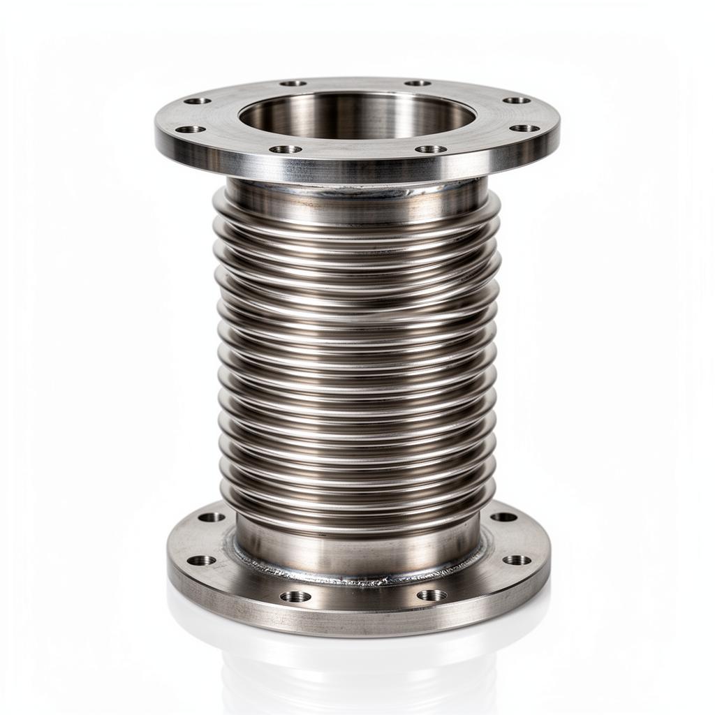
- Axial Bellows: Movement along the longitudinal axis. No tie bars.
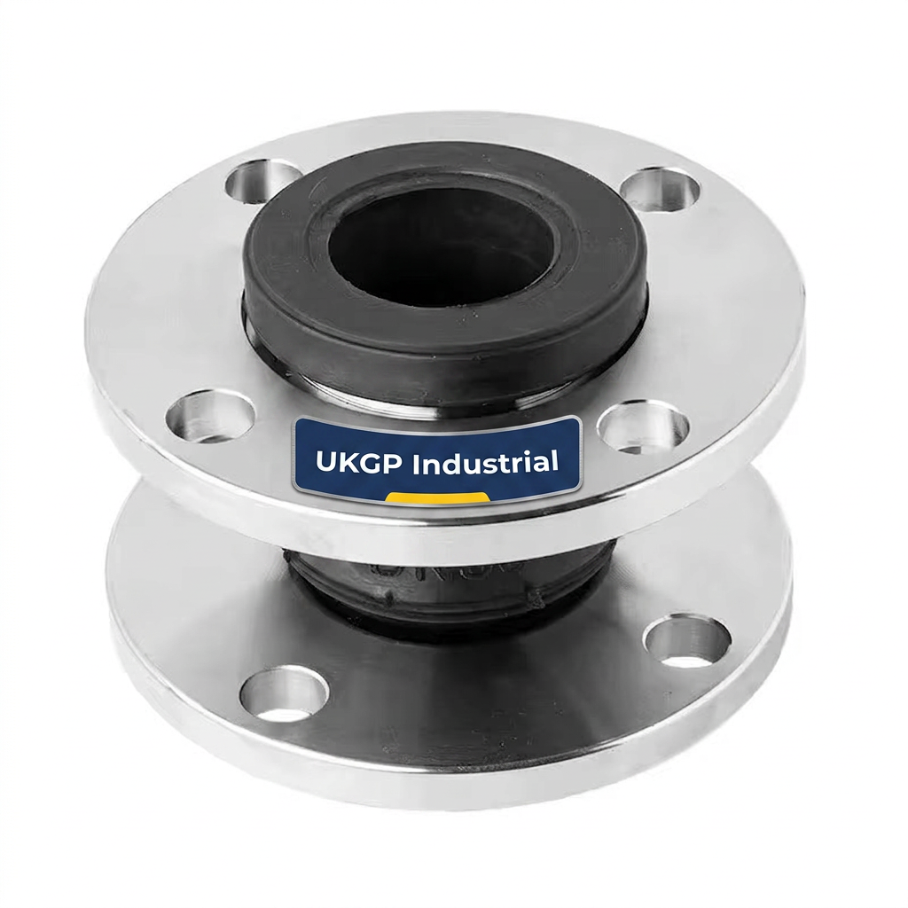
- Tied Lateral Bellows: Movement perpendicular to the axis. Tie bars included.
- Angular Bellows: Hinged or gimballed for rotational movement.
- Universal Bellows: Two bellows joined by a spool to handle large lateral offsets.
Frequently asked questions
How do I calculate the amount of expansion a bellow needs to absorb?
- To calculate thermal expansion (ΔL), use ΔL = L x α x ΔT, where L is the pipe length (m), α is the coefficient of thermal expansion (mm/m/°C), and ΔT is the temperature difference between ambient/installation and maximum operating temperature. Always add a 10-15% safety margin.
What is the temperature limit for EPDM rubber bellows versus stainless steel?
- EPDM rubber bellows are typically rated for 100°C to 110°C. For applications exceeding 110°C, such as high-temperature LTHW or steam, stainless steel bellows (conforming to EN 14917) are mandatory.
Why is anchor point calculation critical for expansion bellows?
- Main anchors must be sized to withstand the 'Pressure Thrust' (cross-sectional area of the bellow multiplied by the test pressure) plus the 'Spring Force' of the bellow and pipe friction. On a 150mm line at 10 bar, pressure thrust can exceed 30kN.
Can an axial bellow handle lateral pipe misalignment?
- No. Axial bellows are designed to be compressed and extended along the longitudinal axis. Forcing them to accommodate lateral offset or angular misalignment will lead to premature fatigue and eventual bursting of the convolutions. For multi-plane movement, use lateral or universal tied bellows.
What is the purpose of tie bars on a lateral expansion joint?
- Tie bars are used to prevent the bellow from over-extending due to pressure thrust. In lateral bellows, tie bars absorb the pressure load, meaning the anchors only need to handle the force required to deflect the bellow, not the full system pressure thrust.