The Fundamentals of Thermal Compensation in Heat Networks
In district heating applications, steel pipework undergoes significant dimensional changes as it transitions from ambient installation temperatures to peak operating temperatures, which can exceed 120°C in Class C networks. Without adequate compensation, the resulting longitudinal forces can exceed the yield strength of the steel or destroy fixed equipment such as heat exchangers and pumps. Expansion bellows serve as the primary mechanism for absorbing this movement within a compact footprint, compared to the larger space requirements of natural expansion loops.
The design process begins with the Expansion Joint Manufacturers Association (EJMA) standards, which provide the mathematical framework for calculating bellows life cycles and spring rates. In the UK, designers must also ensure compliance with the Pressure Equipment Directive (PED) and relevant British Standards. The thermal expansion of carbon steel is approximately 1.2mm per metre per 100°C temperature rise; over a 50-metre run, this equates to 60mm of movement, necessitating high-precision compensation hardware.
Engineers must distinguish between internal plant-room bellows and those integrated into buried pre-insulated pipe systems. While plant-room bellows are accessible for inspection, buried expansion joints are often 'designed for life' and must be protected by bespoke casings or positioned within accessible chambers. The choice of bellows material—typically Grade 316L or 321 stainless steel—is dictated by the chemical composition of the primary circuit water and the risk of stress corrosion cracking.
- Calculation of thermal growth based on ΔT between ambient and maximum operating temperature.
- Analysis of main anchor (MA) and intermediate anchor (IA) loads.
- Selection of bellows type: Axial, Lateral, Angular, or Gimbal.
- Environmental factors: buried (pre-insulated) vs. plant-room installation.
Categorisation of Bellows by Movement Profile
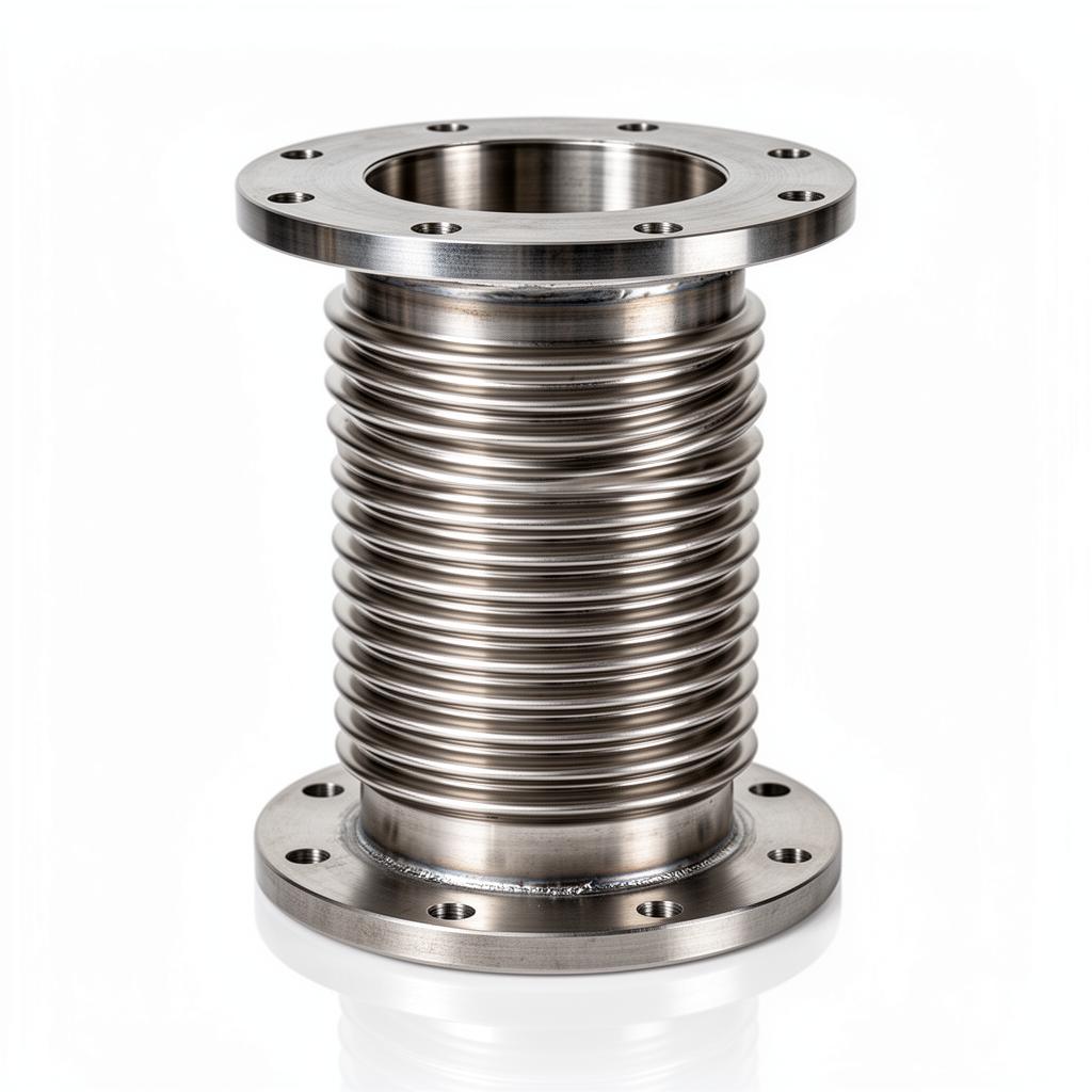
The most common configuration in straight DHN runs is the axial expansion joint. These units are designed to compress as the pipe expands. However, axial joints exert significant 'pressure thrust' on the anchors. This thrust is a product of the internal pressure multiplied by the effective cross-sectional area of the bellows. Designers must ensure that main anchors are sized to withstand the sum of the pressure thrust, the bellows spring rate force, and the frictional resistance of the pipe guides.
Lateral and angular expansion joints are employed where pipework changes direction. Lateral joints are particularly effective in absorbing large amounts of movement in 'Z' or 'L' shaped configurations. Because they are typically fitted with tie rods, the pressure thrust is contained within the unit itself, significantly reducing the load on the building's structural anchors. This makes them ideal for retrofit applications where existing walls may not support the high loads of axial systems.
Universal bellows are utilised when multi-plane movement is anticipated, such as at building entry points where differential settlement between the district heating trench and the plant-room foundation may occur. These units can absorb axial, lateral, and angular movement simultaneously. However, they require careful support design to ensure that the weight of the centre spool does not induce premature fatigue on the convolutions.
- Axial: Simplest form, absorbs movement along the longitudinal axis.
- Lateral: Designed to absorb movement perpendicular to the pipe axis.
- Angular: Permits rotation around a central pin or hinge point.
- Universal: Combines multiple movements using two bellows joined by a centre spool.
Material Selection and Corrosion Resistance
Material integrity is the most critical factor in DHN bellows longevity. For the bellows element (the convolutions), austenitic stainless steels like Grade 316L are standard due to their balance of flexibility and corrosion resistance. In high-temperature applications or where there is a risk of chloride-induced stress corrosion cracking, higher-specification alloys such as Inconel or Monel may be required, though these are rare in standard UK district heating.
The thickness of the bellows material is a compromise between pressure containment and flexibility. To achieve high pressure ratings (PN16, PN25, or PN40) while maintaining a low spring rate, manufacturers use multi-ply construction. Instead of one thick wall, several thin layers of stainless steel are formed together. This allows the bellows to remain flexible under high pressure, significantly increasing the fatigue life (the number of thermal cycles the unit can withstand before failure).
For flange connections, BS EN 1092-1 carbon steel flanges are typical, often with a protective coating to prevent external atmospheric corrosion in damp plant-room environments. For buried applications, butt-weld ends are the industry standard. This eliminates the risk of gasket failure and ensures a continuous, welded system. When specifying stainless steel expansion joints, engineers must also consider the metallurgy of the internal liner, which should match or exceed the bellows material to prevent galvanic corrosion.
Standards and Regulatory Compliance in the UK
In the UK building services sector, compliance with the Pressure Equipment (Safety) Regulations is mandatory. Metal bellows are classified as 'pressure accessories' and must be CE or UKCA marked depending on their volume and pressure rating. Design must follow EN 14917, which replaces many older national standards and defines the requirements for design, manufacture, and testing of metallic bellows expansion joints.
Water quality management is another critical regulatory area. BSRIA BG50 provides guidelines on water treatment to prevent corrosion in closed-loop systems. Poorly managed water chemistry—specifically high oxygen levels or excessive chlorides—can lead to pitting corrosion in the thin stainless steel convolutions, causing rapid failure. Expansion joints are often the 'weak link' in a system due to their thin wall thickness, making chemical dosing and monitoring essential.
District heating networks often operate under the scope of BS EN 13941. This standard governs the design and installation of bonded pre-insulated pipe systems. When expansion bellows are integrated into these systems, they must be housed in a way that allows for the thermal movement of the service pipe without compromising the integrity of the polyurethane insulation or the outer HDPE casing. This often involves specialized 'expansion cushions' or bellows pits.
- BSRIA BG29/21 for pre-commissioning cleaning protocols.
- BSRIA BG50 for domestic and district heating water quality.
- EN 14917: Metal bellows expansion joints for pressure applications.
- BS EN 13941: Design and installation of pre-insulated pipe systems.
Installation Requirements: Anchors and Guides Connectivity
The failure of an expansion joint is rarely due to a defect in the bellows itself, but rather incorrect pipework geometry and anchoring. An axial bellows must be installed between two fixed points (anchors). Main Anchors (MA) are required at pipe ends, changes in direction, and between bellows of different sizes. Intermediate Anchors (IA) can be used to divide long runs into smaller sections, provided only one axial bellows is installed between any two anchors.
Pipe guiding is equally vital. Without proper guiding, the internal pressure will cause the bellows to 'squirm'—a phenomenon where the convolutions deform laterally, leading to immediate failure. The first pipe guide must be located within a distance of 4 nominal diameters (4D) from the expansion joint. The second guide must be within 14 nominal diameters (14D). This ensures that the pipe enters the bellows in a perfectly linear fashion, preventing eccentric loading.
During installation, it is critical not to use the bellows to compensate for pipework misalignment. Bellows are precision-engineered components, not 'gap fillers'. Forcing a bellows into a misaligned gap introduces 'cold-set' stress that reduces the available movement and fatigue life. If a system requires 'cold-drawing' (pre-stressing the bellows to 50% of its total movement), this must be done according to a strict engineering protocol to ensure the bellows operates within its designed neutral zone during peak heat.
Maintenance and Life Cycle Monitoring
Expansion bellows are often 'fit and forget' components, but in critical district heating infrastructure, they require a formal inspection regime. BSRIA recommendations suggest annual visual inspections of all accessible expansion joints. Inspectors should look for signs of mechanical damage, such as dents in the convolutions, which act as stress concentrators and significantly reduce the fatigue life of the unit.
In older systems, the buildup of magnetite or scale between the convolutions can restrict movement, effectively 'locking' the bellows and transferring thermal loads back to the anchors. During system flushes (per BSRIA BG29/21), it is essential to ensure that debris is not trapped. If a system has been operational for more than 15-20 years, a risk-based assessment should be conducted to determine if bellows should be replaced during planned outages, as the stainless steel may have reached its fatigue limit.
For multi-ply bellows, a small 'weep hole' may be present in the outer reinforcement rings. If moisture or system fluid is detected here, it indicates a failure of the inner ply. While the outer plies may contain the pressure temporarily, this is a signal for immediate replacement. Monitoring the displacement of the bellows during heat-up and cool-down cycles is also a useful way to verify that the pipe guides and anchors are functioning as intended.
- Visual inspection for 'rainbowing' or discoloration indicating over-temperature.
- Checking for convolution 'bottoming out' (over-compression).
- Inspection of tie-rods and anchors for signs of stress or movement.
- Monitoring for 'weeping' or leaks, particularly in multi-ply units.
Determining Flow Liners and External Covers Connectivity
Internal flow liners (sleeves) are essential for district heating systems where flow velocities exceed 5 m/s. The liner prevents the turbulent flow of water from inducing high-frequency vibration in the bellows convolutions. This vibration can lead to 'fatigue cracking' within weeks of commissioning. Liners also protect the convolutions from erosion if the heating medium contains suspended solids or abrasive particulates. It is crucial to note that liners are directional; an arrow is typically etched on the bellows outer hardware to indicate the required flow direction.
External covers (shrouds) provide mechanical protection for the convolutions. In a busy plant-room environment, an unprotected bellows is vulnerable to impact from ladders, tools, or falling debris. Furthermore, external covers protect the stainless steel from external chloride contamination—for example, from dripping insulation or cleaning chemicals used on the plant-room floor. For buried bellows, heavy-duty telescopic covers are used to prevent soil ingress while allowing the bellows to move freely.
When specifying a liner, the impact on the internal diameter (ID) must be considered. A liner slightly reduces the flow area, which may insignificantly increase the pressure drop across the joint. However, the protection it offers to the bellows usually outweighs the hydraulic penalty. Designers must also ensure that there is sufficient clearance between the liner and the bellows wall to prevent the liner from jamming when the bellows undergoes lateral or angular movement.
Thermal Efficiency and Insulation Jackets Connectivity
While expansion bellows are essential for mechanical integrity, they are often a source of significant heat loss in a district heating plant-room. Standard rigid insulation is difficult to apply over a bellows because it must allow for the unit's expansion and contraction. Consequently, many bellows are left uninsulated, leading to energy waste and increased ambient temperatures in the plant-room. This is contrary to the efficiency goals of a modern DHN.
The solution is the use of bespoke, flexible thermal insulation jackets. These jackets are typically made from silicone-coated glass cloth with a mineral wool infill. They are designed to 'bellow' along with the expansion joint, maintaining a tight thermal seal throughout the movement range. For UKGP Industrial installations, these jackets are often specified to be easily removable via Velcro or buckle straps to facilitate the annual visual inspections required for the bellows convolutions.
It is vital that the insulation jacket does not interfere with the movement of the bellows or the tie rods. If an insulation jacket is poorly fitted, it can get caught in the convolutions, leading to uneven compression. Furthermore, for stainless steel bellows, the insulation materials must be 'low chloride' to prevent the risk of external stress corrosion cracking if the jacket becomes wet. Correctly specified insulation can reduce heat loss by up to 90% compared to an uninsulated expansion joint.
Anchor Load Calculations and Structural Integration
The design of anchors in a district heating network is a high-stakes engineering task. A 200mm diameter axial bellows operating at 10 bar generates a pressure thrust of approximately 3,500kg (35kN). This force is constant as long as the system is pressurised. When the pipe expands, the bellows 'spring rate' adds further force. For a high-pressure, large-bore DHN, the total force on a main anchor can easily exceed 100kN. This must be transferred into the building's structural slab or a dedicated concrete thrust block.
Structural engineers must be consulted to ensure the plant-room floor or walls can sustain these point loads. In many cases, it is preferable to use tied lateral expansion joints in 'L-bends' to eliminate pressure thrust on the building structure. Because the tie rods take the pressure load, the anchors only need to handle the relatively small force required to move the bellows. This approach is frequently used when connecting district heating mains to lighter-weight modular plant-room skids.
Finally, the thermal movement of the pipe must be calculated using the 'maximum possible' temperature range (e.g., from a -5°C winter installation temperature to a 120°C flow temperature). Relying on the 'average' operating temperature can lead to under-specification. By following EJMA guidelines and utilizing UKGP Industrial technical data, consultants can ensure that every anchor, guide, and bellows unit is sized for the extreme conditions the network will face over its 30+ year design life.
Frequently asked questions
What flange standards are typically required for district heating bellows?
- Standard PN16 or PN25 flanges to BS EN 1092-1 are typical. However, for buried district heating pipework, butt-weld ends are preferred to eliminate the risk of flange gasket failure in inaccessible locations.
Can standard rubber bellows be used on primary district heating circuits?
- No. While standard copper-filled or reinforced rubber bellows are common in building services, district heating primary circuits (often operating at 95°C-120°C) typically require multi-ply stainless steel bellows to EN 14917 to handle the pressure/temperature profile and chemical treatment levels.
How does BSRIA BG29/21 impact bellows selection?
- BSRIA BG29/21 is the industry standard for pre-commissioning cleaning. Expansion joints must be protected during this phase; bypass loops or temporary spool pieces are often used to prevent debris from settling in the convolutions during high-velocity flushes.
What is the '4D/14D' rule in bellows installation?
- Guided pipe supports must be used on both sides of an axial expansion joint. The first guide should be within 4 pipe diameters (4D) of the joint, and the second within 14 diameters (14D) to prevent 'squirm' or buckling under pressure.
When should an internal sleeve be specified?
- Internal sleeves (liners) should be specified if flow velocities exceed 5m/s for liquids or if the medium is abrasive. They prevent resonant vibration of the bellows convolutions and reduce erosion.