Understanding the mechanics of thermal expansion
Before selecting a bellows, the engineer must accurately calculate the total linear expansion of the pipework. For carbon steel, this is typically 0.012mm/m/°C, while copper and stainless steel exhibit higher rates. In a typical UK LTHW system operating with a 60°C delta-T, a 50-metre run of steel pipe will expand by approximately 36mm. This movement must be absorbed without exceeding the yield strength of the pipe or the design limits of the connected plant.
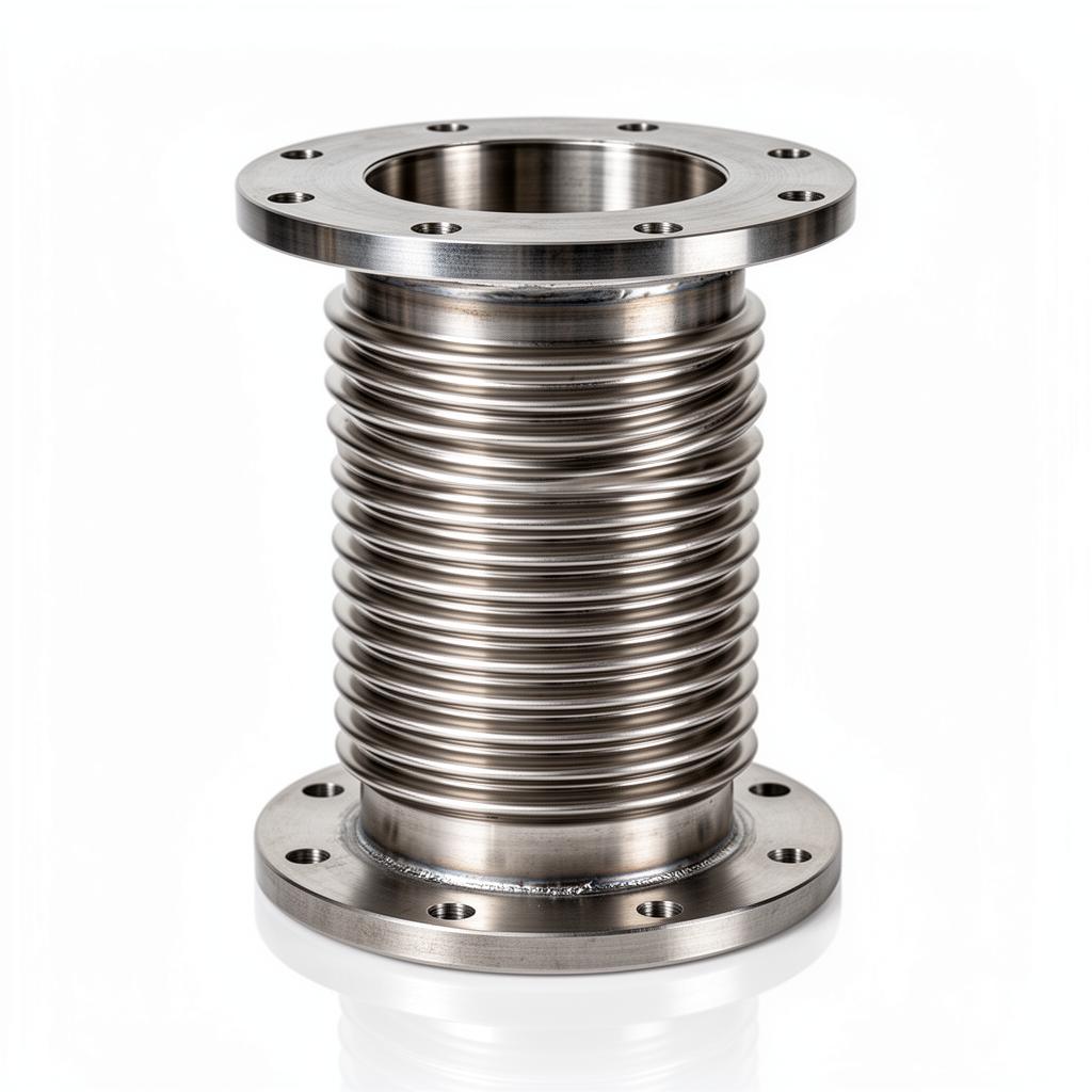
The choice between bellows and natural expansion loops (offsets) is often dictated by space. While loops are maintenance-free, they require significant plant-room footprint. Expansion bellows provide a compact alternative but introduce 'pressure thrust' forces into the system. Engineers must distinguish between axial, lateral, and angular movements, as each requires a specific bellows geometry to ensure the assembly does not succumb to fatigue failure.
Pressure thrust is the most critical calculation. When a bellows is pressurised, it acts like a piston, attempting to push the pipework apart. This force is the product of the system pressure and the effective cross-sectional area of the bellows (not the pipe ID). For a DN200 bellows at 10 bar, this force can exceed 40kN, requiring substantial structural anchors that must be coordinated with the structural engineer during the RIBA Stage 4 design.
- Axial movement: Compression or extension along the longitudinal axis.
- Lateral deflection: Displacement perpendicular to the axis (shear).
- Angular rotation: Bending of the bellows axis into an arc.
- Torsional stress: Twisting around the axis (which must be avoided for metal bellows).
Rubber expansion joints: Selection and limits
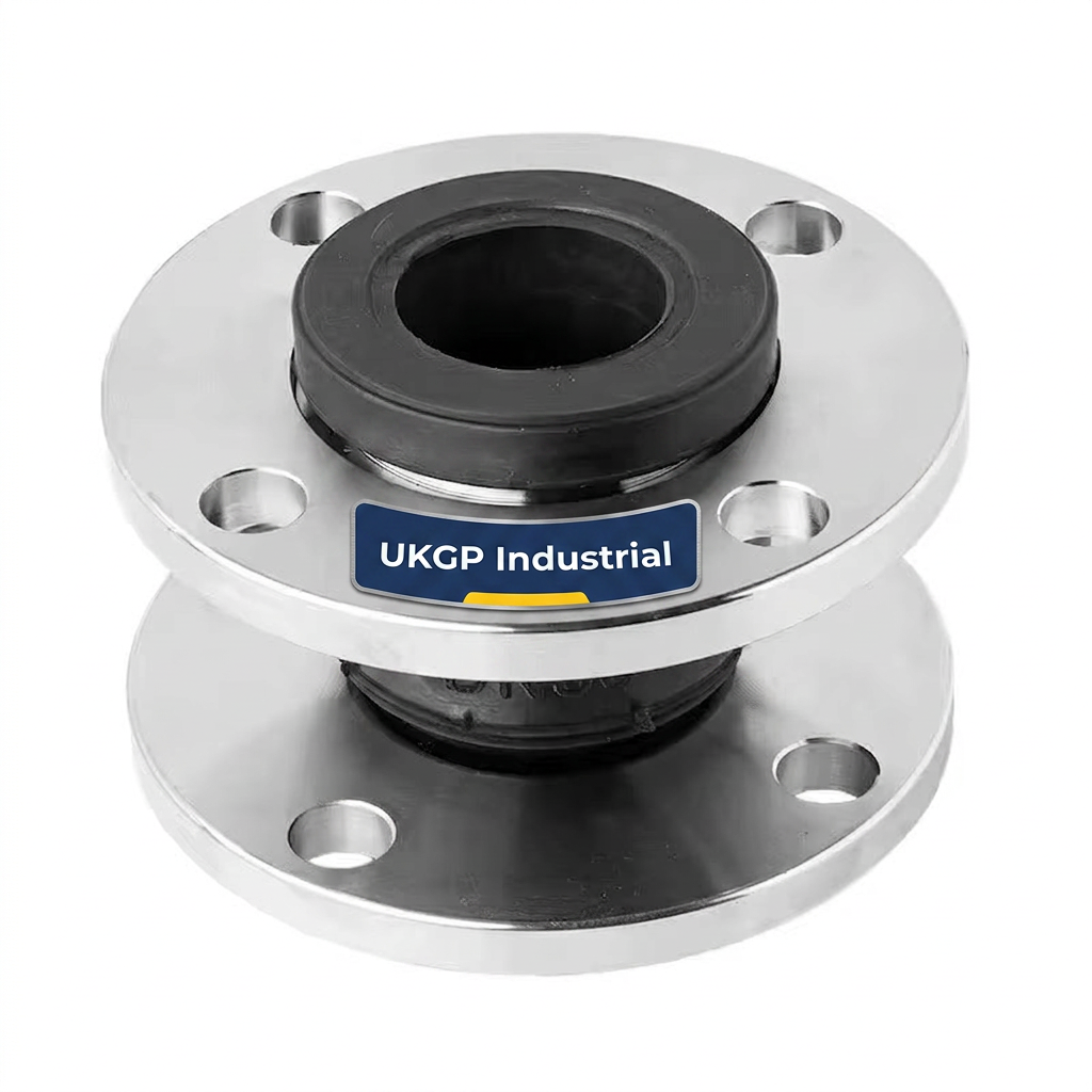
Rubber bellows, often referred to as 'anti-vibration' joints, are the primary choice for pump connections and plant-room headers. Their primary benefit is the ability to absorb multi-directional movement and isolate high-frequency vibration and noise. In accordance with BSRIA BG29/21, rubber joints are essential for preventing the transmission of mechanical vibration into the building structure.
However, rubber has strict temperature-pressure envelopes. While an EPDM bellows might be rated for 16 bar at 20°C, this rating may drop significantly at 90°C. Standard UK commercial LTHW systems usually operate within these limits, but secondary district heating circuits or high-temperature process lines may require metal alternatives. It is also vital to specify 'tied' or 'untied' units; tied rubber bellows (fitted with limit rods) prevent the joint from over-extending under pressure thrust but restrict axial movement, focusing instead on lateral vibration.
The internal reinforcement of the rubber—typically nylon or aramid cord—is what provides the pressure rating. Engineers should ensure that the bellows are manufactured with integrated steel wire reinforced collars to prevent the bellows from pulling out of the flanges under high-pressure surges. For vacuum applications, such as pump suction lines, internal vacuum rings are necessary to prevent the bellows from collapsing inwards.
- EPDM (Ethylene Propylene Diene Monomer): Standard for LTHW and CHW; ozone and weather resistant.
- Nitrile (NBR): Essential for oil-contaminated lines, fuels, and fats.
- Butyl: Low permeability, suitable for compressed air and some chemicals.
- Viton (FKM): High temperature and aggressive chemical resistance for process applications.
Frequently asked questions
Can I use a PN16 rated rubber bellows for a 110°C LTHW system?
- No. PN16 flanges refer to the pressure rating, but the temperature derating of the bellows material must be checked. EPDM rubber bellows, for instance, lose pressure integrity as temperatures exceed 70°C, even if the flange is rated for 16 bar.
Why is the 'cold draw' or 'installation gap' so important for axial bellows?
- The 'neutral' or 'installed' length is critical. If a bellows is stretched or compressed to fit a gap that is too wide or narrow, it uses up its design movement allowance before the system even heats up. This leads to premature bellows failure and stress on the pipework.
Should I use rubber or metal bellows for a vertical riser?
- Generally, metal bellows (BS EN 14917) are preferred for high-rise risers due to higher pressure ratings and fire safety. However, rubber bellows provide superior noise and vibration attenuation (acoustic isolation) for pump connections and plant-room headers.
What is the difference between a pipe guide and a pipe support in the context of expansion?
- A guide allows only axial movement, while a support carries the weight of the pipe. All axial expansion systems require the first two guides (G1 and G2) to be placed at specific distances (typically 4D and 14D) from the bellows to prevent squirm or buckling.